Using the pdn line, Using the lo_v_d line, Typical applications – Linx Technologies TXM-xxx-ES User Manual
Page 8
– –
– –
10
11
Using the PDN Line
The Power Down (PDN) line can be used to power down the transmitter
without the need for an external switch. This line has an internal pull-up, so
the module is active when it is held high or simply left floating.
When the PDN line is pulled to ground, the transmitter enters into a low
current (<95µA) power-down mode. During this time, the transmitter
is off and cannot perform any function. The startup time coming out of
power-down is the same as applying V
CC
.
The PDN line allows easy control of the transmitter state from external
components, such as a microcontroller. By periodically activating the
transmitter, sending data, then powering down, the transmitter’s average
current consumption can be greatly reduced, saving power in battery
operated applications.
Using the LO_V_D Line
In many instances, the transmitter may be employed in a battery-powered
device. In such applications, it is often useful to be able to sense a
low-battery condition, either to signal the need for battery replacement or
to power down components that might otherwise operate unpredictably.
Normally, this supervisory function would require additional circuitry, but the
ES Series transmitter includes the function on-board.
The Low Voltage Detect line (LO_V_D) transitions low when the supply
voltage to the transmitter falls below a typical threshold of 2.15VDC.
This output can be tied directly to the module’s PDN line to shut off the
transmitter, or used to indicate the low voltage condition to an external
circuit or microprocessor. The output could also be used to provide a
visual indication of the low power condition via an LED, although a buffer
transistor would generally be required to provide an adequate drive level.
The output can also be monitored in applications with a power supply as a
safeguard against brownout conditions.
Typical Applications
Using the ES Series Transmitter for Analog Applications
The ES Series is an excellent choice for sending analog information,
including audio. The ability of the ES to transmit combinations of analog
and digital content opens many new opportunities for design creativity.
Simple or complex analog signals within the specified audio bandwidth
and input levels may be connected directly to the transmitter’s DATA line.
The transmitter input is high impedance (500k
Ω
) and can be directly driven
by a wide variety of sources, ranging from a single frequency to complex
content, such as audio.
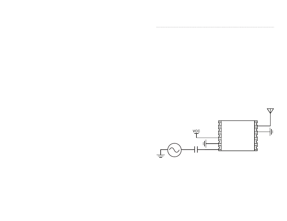
Analog sources should provide 0V to no more than 5V
P-P
maximum
waveform and should be AC-coupled into the DATA line. The size of the
coupling capacitor should be large enough to ensure the passage of all
desired frequencies. Since the modulation voltage applied to the DATA line
determines the carrier deviation, distortion can occur if the DATA line is
over-driven. The actual level of the input waveform should be adjusted to
achieve optimum in-circuit results.
0.1µF
0-Vcc Audio Source
PDN
LADJ
VCC
LO_V_D
/CLK SEL
/CLK
GND
DATA
ANT
GND
1
2
3
4
5
6
7
8
9
10
Figure 12: AC Coupling An Audio Source to the ES Series Transmitter