Pin assignments – Linx Technologies LICAL-ENC-MS001 User Manual
Page 5
–
–
–
–
4
5
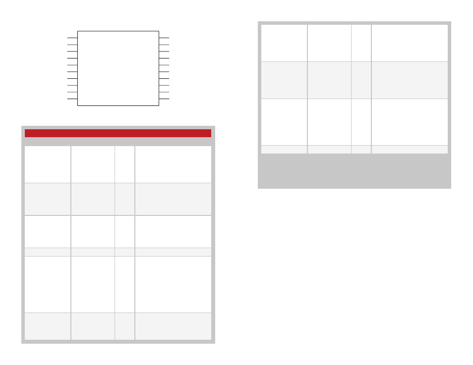
Pin Assignments
Figure 6: MS Series Encoder Pin Assignments
10
MODE_IND
O
Mode Indicator Output. This line
is activated while the encoder
is in Create Mode, allowing the
connection of an LED. The line is
high for the entire time the encoder
is in Create Mode, indicating that it
is creating a new Address.
11
CREATE_ADDR
I
Create Mode Selection Line. When
this line is taken high, the encoder
enters Create Mode and randomly
generates a new Address. The
Address continuously randomized
while this line is high, and is saved
as soon as the line is taken low.
12
SEND
I
Encoder Send Data Line. When
this line goes high, the encoder
records the states of the data
lines, retrieves the Address from
memory, assemble sthe packet,
and outputs it as a serial bit stream
on the DATA_OUT line at the baud
rate selected by the states of the
SEL_BAUD lines.
15, 16
V
CC
Supply Voltage
None of the input lines have internal pull-up or pull-down resistors. The input lines must
always be in a known state (either GND or V
CC
) at all times or the operation may not
be predictable. The designer must ensure that the input lines are never floating, either
by using external resistors, by tying the lines directly to GND or V
CC
, or by use of other
circuits to control the line state.
Pin Descriptions
Pin Number
Name
I/O
Description
1, 2, 13, 14, 17–20
DO–D7
I
Data Input Lines. The state of
these lines are captured when
the SEND line goes high and
encoded for transmission. Upon
successful reception, these states
are reproduced on the outputs of
the decoder.
3
SEL_BAUD0
I
Baud Rate Selection Line 0. This
line along with SEL_BAUD1 sets
the baud rate of the serial data
stream to one of 4 possible rates.
The rate must be set before power
on.
4
SEL_BAUD1
I
Baud Rate Selection Line 1. This
line along with SEL_BAUD0 sets
the baud rate of the serial data
stream to one of 4 possible rates.
The rate must be set before power
on.
5, 6, 7
GND
Ground
8
TX_CNTL
0
External Transmitter Control Line.
This line goes high when the SEND
line goes high, and low when the
SEND line goes low. This can be
used to power up an external
RF or infrared transmitter when
the encoder is sending data, and
power it down when the encoder
is asleep. It can also be used to
drive a LED for visual transmit
indication.
9
DATA_OUT
0
Serial Data Output. The encoder
outputs a serial data stream on this
line. This line can directly interface
with all Linx RF transmitter
modules.
Figure 7: Pin Descriptions
LICAL-ENC-MS001
D6
D7
SEL_BAUD0
SEL_BAUD1
GND
GND
GND
TX_CNTL
DATA_OUT
MODE_IND
D5
D4
D3
D2
VCC
VCC
D1
D0
SEND
CREATE_ADDR
1
2
3
4
5
6
7
8
9
10
11
12
13
14
15
16
17
18
19
20