Typical applications, System example – Linx Technologies LICAL-ENC-MS001 User Manual
Page 9
–
–
–
–
12
13
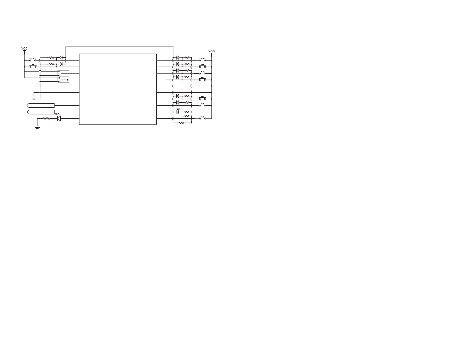
Typical Applications
The MS encoder is ideal for registering button presses in remote control
applications. An example application circuit is shown in Figure 11.
In this circuit, SPDT switches are used to select the baud rate so that
pull-down resistors are not needed. The data lines are connected to
buttons and when any button is pressed, the SEND line is pulled high and
causes the encoder to transmit. The diodes are used to prevent the voltage
on one data line from appearing on another data line.
If only one data line is needed, then it can be tied directly to the SEND line
without the need for the diodes.
None of the inputs have pull-up or pull-down resistors internally, so 100k
Ω
pull-down resistors are used on the data lines, SEND, and CREATE_ADDR.
These resistors are used to pull the lines to ground when the buttons are
not being pressed and ensure that they are always in a known state and
not floating. Without these resistors, the state of the lines could not be
guaranteed and encoder operation may not be predictable.
An LED is attached to the MODE_IND line to provide visual feedback to
the user that an operation is taking place. This line sources a maximum of
25mA.
Outgoing encoded data is sent out of the DATA_OUT line at the baud rate
determined by the state of the SEL_BAUD lines. This line can be connected
directly to the DATA_IN line of a Linx transmitter, used to modulate an
infrared diode, or connected to any other serial transmission medium.
To Transmitter
100k
100k
220
100k
100k
100k
100k
100k
100k
100k
LICAL-ENC-MS001
D6
D7
SEL_BAUD0
SEL_BAUD1
GND
GND
GND
TX_CNTL
DATA_OUT
MODE_IND
D5
D4
D3
D2
VCC
VCC
D1
D0
SEND
CREATE_ADDR
1
2
3
4
5
6
7
8
9
10
11
12
13
14
15
16
17
18
19
20
220
To Transmitter PDN
100k
Figure 11: MS Series Encoder Application Circuit
The TX_CNTL line is connected to the PDN line of a Linx transmitter. This
is used to place the transmitter into a low power state when not in use. An
LED can also be connected to the TX_CNTL line to provide visual indication
that the encoder is sending data.
In this example, the data lines are pulled high by simple pushbutton
switches, but many other methods may be employed. Trace contacts,
reed switches or microcontrollers are just some examples of other ways of
pulling the data lines high. The flexibility of the encoder combined with the
associative options of the matching decoder opens a whole new world of
options for creative designers.
System Example
The first step in using the encoder is to set the baud rate using the SPDT
switches or simply tying the lines to supply or ground. Next, a unique
Address is created by pressing and holding the button connected to the
CREATE_ADDR line for as long as desired. While the button is held, the
LED is on indicating that the Address is being created. Once the button is
released, the LED starts flashing. The data buttons that the encoder is to
access are now pressed. Pressing the CREATE_ADDR button again makes
the encoder save the new Address and Control Permissions, turn off the
LED, and go to sleep.
The decoder must now learn the Address for the system to be operational.
Please see the decoder data guide for instructions on how to do this. The
MS Series Master Development System implements this system, so please
see the User’s Guide for more system information and circuit schematics.