Logitek Electronic Systems Pilot User Manual
Page 15
GPI connections are on a single DB25 connector on the rear of the Pilot frame. As wiring schemes
vary from station to station, these cables are not supplied with the surface, but are available from
Logitek Electronic Systems
. They can also be purchased from local suppliers in the required form.
See Appendix C for connector pinouts.
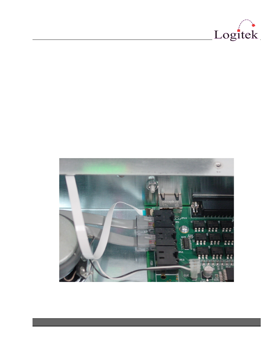
Internal Module Connections
Inside the frame, four RJ45 port connectors are provided for connecting to each Fader module.
These are provided as a straight-through flat cable, however any RJ45 patch will suffice.
The Monitor module connects to the internal PCB via the included flat rainbow ribbon cable. The
connectors are keyed to ensure you cannot reverse the cable.
The Meter has a short flat cable that connects directly to the Pilot frame motherboard. This is
plugged into the connector labeled JP4. The cable length is suitable to mount the Meter behind the
Pilot frame. The Meter cannot be located elsewhere due to its cable requirement.
Logitek Pilot Reference Manual
Figure 5: Internal Connections
15