Fig.11, Fig.12 – Medal Sports WMUS1358108 User Manual
Page 13
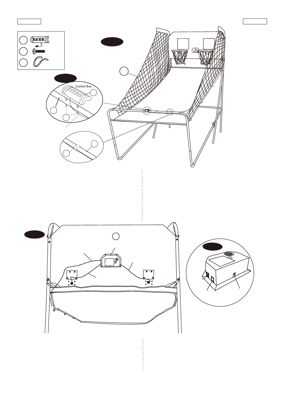
FIG. 12
FIG.11
17. Attach the Control Box (#16) to middle of the
Tube - 11
(#11) using two Bolts (#30) as shown in FIG.11A.
18. Run the rest of the Control Wire through the loops on
the Ball Return Net (#35). Place the Control Wire on
the
Tube - 11
(#11) using the Self-Stick Straps (#34)
as shown in FIG.11.
FIG.11
17. Adjunte la Caja de Control (#16) al medio del Tubo - 11
(#11) usando 2 Cerrojos (#30) como mostrado en la
FIG. 11A.
18. Gire el resto del Cable de Control por las curvas de la
Rampa de Pelota con Redes Lateral (#35). Coloque el
Cable de Control sobre el Tubo - 11 (#11) usando las
Correas de Auto-Vara (#34) como mostrado en la FIG.11.
www.themdsports.com
1358108
12
(Continúe en la siguiente página.)
(Continued on the next page.)
Español
English
FIG.12
19. Connect the Sensor Wire from Switch Sensor (#15) to
the Electronic Scorer (#14) as shown in FIG. 12.
Connect the Control Wire to the Electronic Scorer
(#14) as shown in FIG.12 and 12A.
FIG.12
19. Conecte el Cable de Sensor desde el Sensor de
Interruptor (#15) al Marcador Electrónico (#14) como se
indican en FIG. 12.Conecte el Cable de Control al
Marcador Electrónico (#14) como se indican en
FIG.12 y 12A.
14
Sensor wire
/ Cable de sensor
Sensor wire
/ Cable de sensor
Electronic Scorer
/ Cable de Control
Control Wire
/ Cable de Control
FIG. 12A
ON / OFF
ENCENDIDO / APAGADO
CONTROL
WIRE /
CONTROL
CABLE
VISITOR / VISITANTE
Control Wire
/ Cable de
Control
X1
16
X2
30
X2
34
FIG.11
FIG.11A
11
16
34
30
11
35