Operation flow chart – Precision Digital PD562 User Manual
Page 12
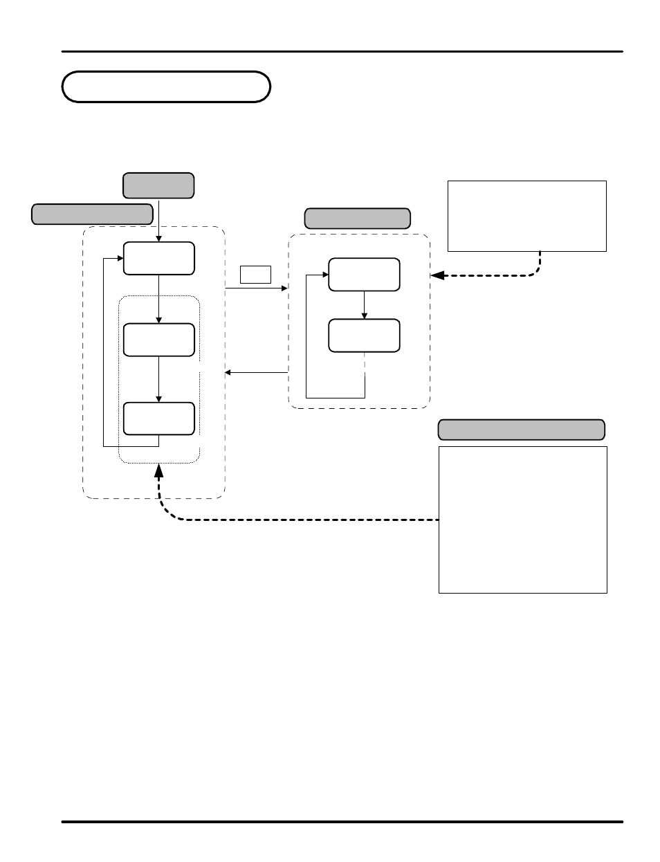
4. Operation Flow Chart
Operation Display
Power On
Group Display
note 1: Initial display when the unit is turned on.
note 2: Only displayed when User Screen 1 is set in US1.
This is set to PV.LO by default.
note 3: Only displayed when User Screen 2 is set in US2.
This is set to PV.HI by default.
When setting controller
parameters, G.IN should be set
up prior to any other parameters.
US1 and US2 are set by the user
to display selected parameters in
the operation display. The
parameters to be displayed are set
from parameters US1 and US2 in
G.CTL. The Table of D-
Registers provides the number to
determine what parameter is
displayed by each. Parameters
displayed here may be altered in
this display as they are normally.
PWD
G.CTL
G.IN
ENT key for
3 seconds or
no keystroke
for 60 sec
ENT 3 sec
PV Value
ENT
(note 1)
ENT
US1
US2
(note 2)
(note 3)
User Set Display
S or T
T
PD560 Series Nova Digital Process and Temperature Meter
Instruction Manual
12