Operation flow chart – Precision Digital PD570 User Manual
Page 13
Advertising
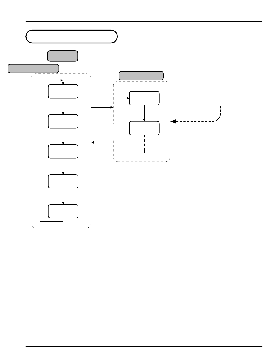
4. Operation Flow Chart
Operation Display
Power On
Group Display
note 1: Initial display at startup.
note 2: Output status for the latching relay.
note 3: The time that has passed since the PV last went over limit.
note 4: Highest PV value. Used only when HI.LO parameter is set to HIGH.
note 5: Lowest PV. Used only when HI.LO parameter is set to Low.
When setting unit parameters,
G.IN should be set up prior to
any other parameters.
ENT 3 Sec
ENT
ENT
ENT
PV Value
SP Value
ENT
PWD
(note 1)
OUT
ON/OFF
TIME
**.**
HI
**.**
LO
**.**
G.CTL
G.IN
ENT key for
3 seconds or
no keystroke
for 60 sec
(note 2)
(note 3)
(note 4)
(note 5)
S or T
T
PD570 Series Nova Process and Temperature Limit Controller
Instruction Manual
13
Advertising
This manual is related to the following products: