Precision Digital PD570 User Manual
Page 19
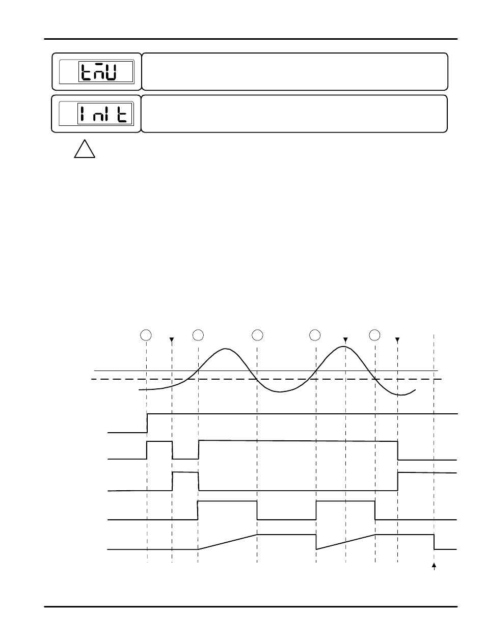
5-2-1 Limit Control Features and Operations
The following illustration shows how each aspect of the limit control functions behave under over limit circumstances.
1. Power supplied to the controller. The OUT LED turns on.
2. The PV surpasses the SP. The OUT LED turns on. the OVER LED turns on. The latching limit control relay de-
energizes. The time begins being recorded.
3. The PV falls below the limit and hysteresis levels. The OVER LED turns off. The time count stops.
4. The PV surpasses the SP. The OVER LED turns on. The time count resets and begins again.
5. The PV falls below the limit and hysteresis levels. the OVER LED turns off. The time count stops.
When the re st button is pressed for 3 seconds, and the PV is below the SP, the OUT LED will turn off, and the limit control
relay will energize.
SP
PV
OUT
LED
Limit
Control
Relay
OVER
LED
Time
Count
Power
to Unit
Reset
Pressed
Time Reset by User
1
5-2-1-1 Operation of Limit Functions when O.ACT = REV, HI.LO = HIGH, R.MD = OFF
Fig 3: Operation of Limit Functions with O.ACT set to REV
This parameter resets mos t parameters to their factory settings. To reset the controller,
set this parameter to ON . After reset, it will return to the OFF setting.
PV
This parameter sets the time units the controller uses for parameters with time
components. This can be set to the format of HH.MM (hours.minutes) or MM.SS
(minutes.seconds). Its default setting is HH.MM.
Most parameters will be reset to their default settings when the controller is initialized. Note the
current settings before thi s is done so they can easily be restored after controller initialization.
!
CAUTION
PV
2
3
4
5
Reset
Pressed
(not accepted)
Reset
Pressed
HYS
ON
OFF
ON
OFF
ON
OFF
ON
OFF
PD570 Series Nova Process and Temperature Limit Controller
Instruction Manual
19