Remote Processing RPC-2300 User Manual
Page 14
DATA MEMORY
CHAPTER 5
Page 12
RPC-2300
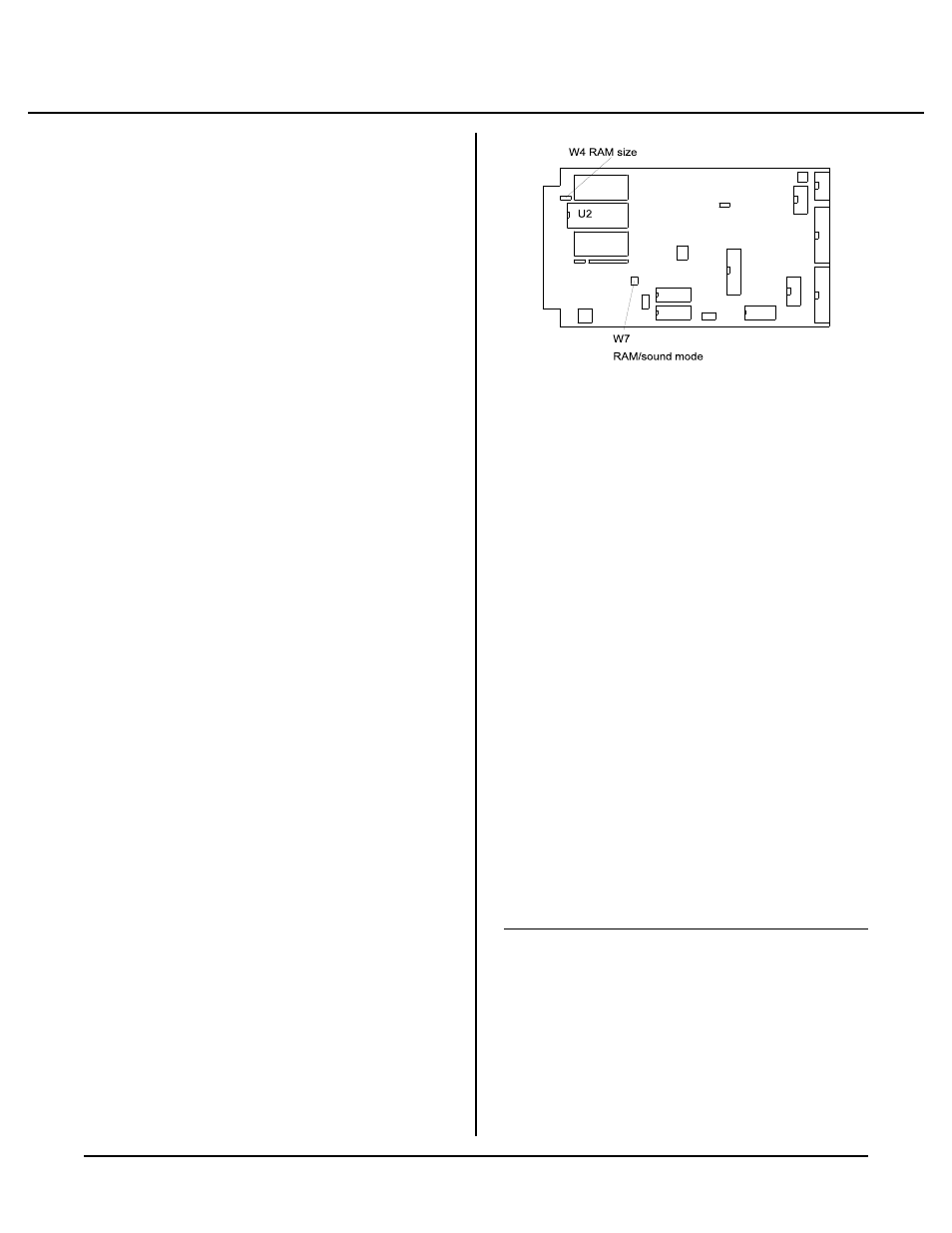
F ig u re 5- 1 J um p er s W 4 an d W 7
INTRODUCTION
The SBS-2300 is available with 128K of RAM. A 512K
RAM m ay be installed at any time. RAM is in socket
U2. RAM m ay be battery backed by installing a DS-
1213D in socket U2. RAM is installed on top of U2.
Battery life will depend upon RAM size, its power
consumption, and am ount of time the board is operating.
Generally, a battery life from 5 to 10 years can be
expected.
This chapter discusses changing RAM, installing a
battery backup for RAM , saving and retrieving
variables, and running assem bly language progr ams.
F i gu r e 5 -1 sh o ws th e lo c at io n of U 2 a n d j um p er s W 4
and W7 (for RA M size change).
Increasing RAM size does not increase the program size
CAM BASIC II can handle. M aximum progr am and
variable size is 30K. Additional RAM does increase the
amount of variable and string storage available using the
PEE K and POK E comm ands.
Due to the memory mapping scheme, the additional
amount of memor y available when a 128K or 512K
RAM is installed is 32K less than the memory size.
Thus, a 128K RA M pr ovides 96K of progr am and d ata
memory and a 512K provides 480K.
If program and data are battery backed, the UNNEW
c o m m an d m ay b e u s ed to r e st or e th e pr o g ra m .
Variables used by the Basic program are clear ed,
howeve r. Cer tain variab les are pr eserve d and data
POKEd into RA M is saved.
There is an interaction between the speaker and when
512K of RAM is installed. This is discussed below
under CHANGING MEMORY.
CHANGING MEMORY
Different types of memory can be installed at any time.
SBS-2300 models come with 128K of RAM installed.
Up to 512K can be installed.
To change a mem ory chip, you need to rem ove the
original chip, install the new one, and set jumpers W 4[2-
3] and W7[1-2][3-4].
To install a new memory chip:
1.
Turn off power to the SBS-2300.
2.
Remove the mem ory chip from U 2.
3.
Orient the chip so pin 1 is closest to the card edge.
Install the new chip into the sock et.
4.
Check and change, as necessary, jumpe r W4 and
W7 to conform to the new m emory.
RAM size
Jumper
W 4
W 7
128K
[1-2]
[1-3][2-4]
512K
[2-3]
[1-2][3-4]
NOTE: The spea ker is disab led when a 512K RA M is
installed.
BATTERY BACKUP
A Dallas Semiconductor DS-1213D is used to battery