Analog i/o chapter 8, Introduction, Connecting analog i/o – Remote Processing RPC-2300 User Manual
Page 24
ANALOG I/O
CHAPTER 8
Page 22
RPC-2300
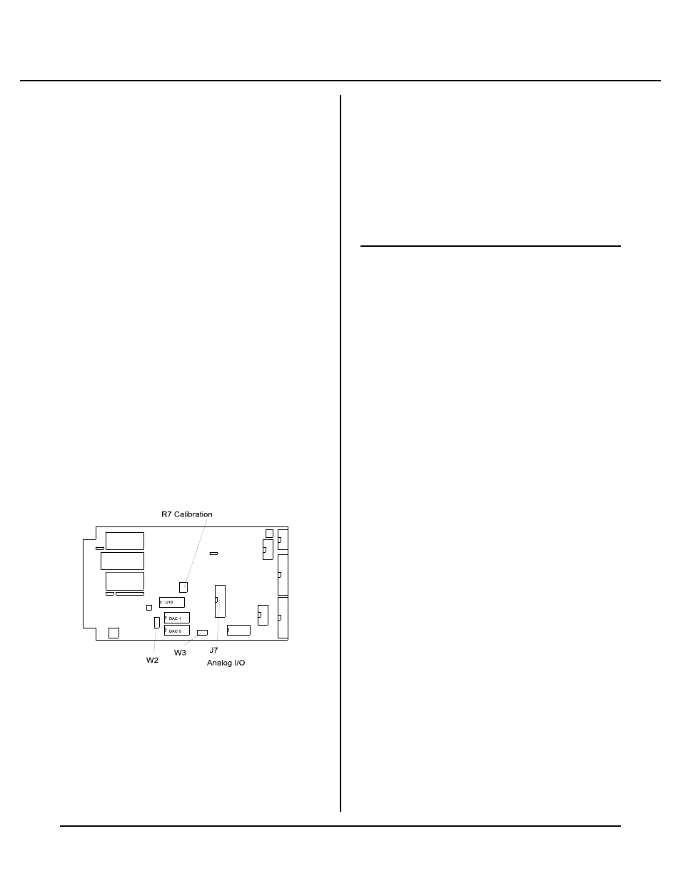
F i gu r e 8 -1 A na lo g I/ O
INTRODUCTION
The SBS-2300 has eight single ended or four differential
analog input channels than can be interfaced to external
analog devices. These channels can be used to measure
voltages from tr ansducers, 4-20 ma cur rent loops,
thermistors, etc. The conver ter reads a voltage and
retur ns a 12 bit (4096 count) num ber in und er a m illi-
sec ond . Inp uts ar e pr ogr am ma ble for 0 to + 5 or ±5
volt, single ended or differential mode.
Additionally, 2 analog outpu t channels w ith 12 bit
accuracy are available. Output voltage is 0-5V, 0-10V,
or ±5V.
Capacitors may be added to pads located adjacent to the
A/D converter (U10). This will help reduce noise on
analog inputs. Capacitor values are application
d e pe n de n t. 0 . 0 1 m fd is a go o d v a lu e to s ta r t f r om .
Higher va lues may be used in extr emely noisy
environments or when time betw een samples is long (>
100 ms).
The AIN function is used to return a voltage while AOT
comm ands an outpu t.
This chapter begins with basic hook-up information, then
proceeds to initialization, data reading, and calibration.
Analog output option is discussed near the end.
CONNECTING ANALOG I/O
Analog I/O interface via J7. The STB-20 terminal board
may be used to br ing signals to terminal blocks.
The following table defines the signal pin out from
analog I/O port J7.
J7
Signal
Pin #
1
CH0 input
2-16
Ground (e ven pins)
3
CH1 input
5
CH2 input
7
CH3 input
9
CH4 input
11
CH5 input
13
CH6 input
15
CH7 input
17
DAC 0 output
18
+ 12V
19
DAC 1 output
20
-12V
Initializing Inputs
The SBS-2300 can hav e up to eight single-ended inputs,
four differential, or a m ixture of single ended and
differential inputs. Each analog input you intend to use
must be initialized. Initialization is performed using the
CON FIG A IN com mand. The syntax is:
CONFIG AIN channel, input, range
Where:
channel
is from 0 to 7 for single-ended inputs or 0-6
for differential. Differential inputs re quire 2 lines.
The channels you specify in a "mixed" application
depends upon what lines are used for single ended
and differ ential. Refer to the table below for single
ended and differen tial channels
Polar ity
+ - + - + - + -
J7 pin #
1 3 5 7 9 11 13 15
Differential
Channel
0 0 2 2 4 4 6 6
Single ended
Channel
0 1 2 3 4 5 6 7
For example , if yo u wanted o ne differ ential input,