Electrode resistance: test c & d, Cont’d.) – Amprobe GP-1 Earth-Tester-Ground-Probe User Manual
Page 12
Electrode Resistance:
Test C & D
(cont’d.)
Page 12
Perform next steps to assure accuracy of the measurements
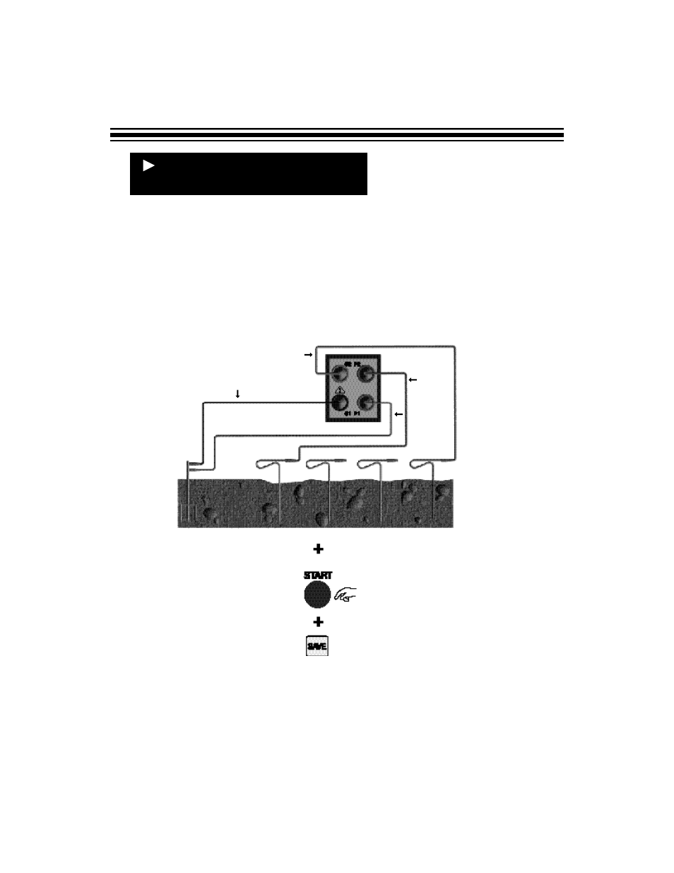
10)Remove P2 (RED) from the 62% rod and clip to the 52% rod.
11)Press and release the START button.
12)Note the value of Rg, or press the SAVE button.The value of Rg will be saved in the
next available memory location. Note the memory location.
BLUE
RED
GREEN
BLACK
P1
C1
P2
C2
52%
62%
100%
72%
8) The possible results are as follows:
• If the test rods are making good contact with the soil, all connections are correct, and the
actual value is less than 2k
Ω
, the measured value (RG) will be displayed in ohms (
Ω
).
Continue to Step 9.
• If the test rods are making good contact with the soil, all connections are correct, and
the actual value is greater than 2k
Ω
, “o.r.” (over range) will be displayed. Recheck
connections, verify rod to soil continuity and treat if necessary, and/or use longer test rods.
9) Note the value of Rg, or press the SAVE button.The value of Rg at P2@67% will be
saved
to the next available memory location. Note the memory location.This is your elec-
trode or grid system resistance.