Conclusion – Amprobe GP-1 Earth-Tester-Ground-Probe User Manual
Page 14
If results on Page 13 are more than 10%, electrodes must be moved farther apar t
(20% - 30% of the distance) and you must retest.
If the change of resistance values measured between the rods is less than 10%, the
resistance value from the point P2 @62% rod is the value of the earth ground resistance.
Explanation:
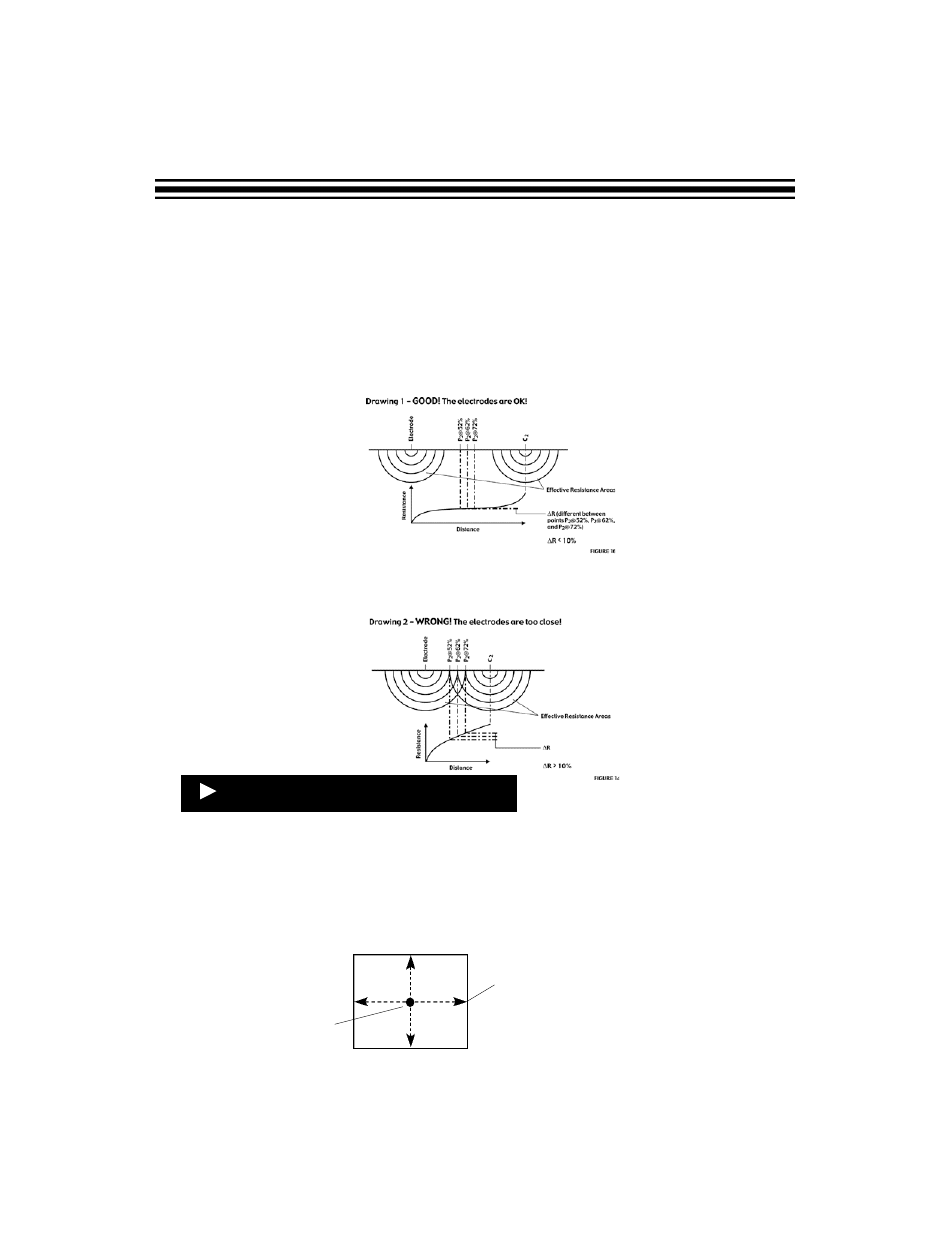
An auxiliary electrode P2 should be outside of the effective resistance areas of both the
existing ground electrode and the auxiliary electrode C2 as shown on the Drawing 1. In this
case the resistance differences calculated using For mula 2 would be less than 10%. Value P2
@62% is the resistance of the ground rod.
If the effective resistance areas overlap, Drawing 2, the resistance differences calculated
using Formula 2 would be more than 10%. In this case value P2@62% contains error and
cannot be used as a value of the electrode ground resistance.
It is recommended to repeat the test at 180 degrees from the initial test.
The average of both values, measured at the P2/62% mark will give you the average earth
ground resistance. If you cannot test at 180 degrees, then test at 90 degrees. If the two
measurements greatly vary from each other, then it may be wise to perform a third and,
possibly, a fourth test.
As an additional test, continue to move electrodes in cross effect (see drawing at right).
This is a good way to check the accuracy of the tests.
Page 14
Conclusion
Existing
ground rod
Directions recommended for
placing testing electrodes to
obtain better accuracy of
measurements.