Dac960prl block diagram (sisl) – Avago Technologies AcceleRAID 150 User Manual
Page 58
DAC960PRL Block Diagram (SISL)
B-4
AcceleRAID 150 Installation Guide
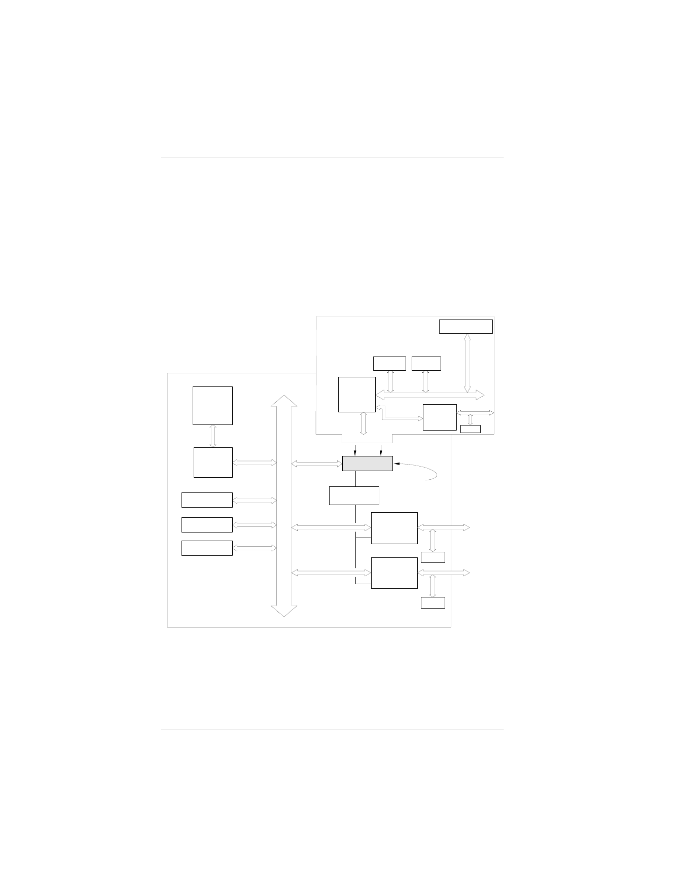
DAC960PRL Block Diagram (SISL)
Figure B-2 (example of a system board block diagram) shows the functional
relationship between the Mylex AcceleRAID 150 Controller and the SCSI-
capable system board. The SCSI chip interrupt line(s) are routed to a PCI bus
slot (shaded to indicate SISL availability) specifically preconfigured to
accept the controller.
The non-shaded PCI bus slots indicate an example of available SCSI
connections that are not intended for SISL activity.
Figure B-2. AcceleRAID and SCSI-Capable System Board (SISL)
CPU
PCI Interface
Control
Logic
PCI Bus Slot
PCI Bus Slot
PCI Bus Slot
PCI Bus Slot
SCSI Protocol
Chip
SCSI Protocol
Chip
Term.
Term.
SCSI Bus
SCSI Bus
PCI Slot
Pre-configured
for AcceleRAID
System Board
Interrupt Logic
RAID FW
NVRAM
Cache Memory
I960RP
AcceleRAID 150
DAC960PRL
Controller
Term.
SCSI
Protocol
Chip