Typical setup, Typical apollo x16 connections, Interconnections 24 apollo x16 hardware manual – Universal Audio Apollo x16 Heritage Edition Rackmount 18x20 Thunder3 Audio Interface with Real-Time UAD Processing User Manual
Page 24
Interconnections
24
Apollo x16 Hardware Manual
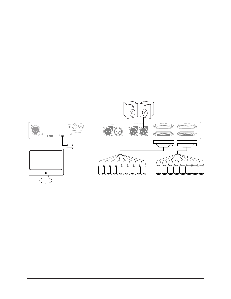
Typical Setup
This diagram illustrates an Apollo x16 example system.
Key points for this example:
• Either Thunderbolt 3 port can be used for the host computer connection
• The Monitor outputs are connected to powered monitors (or an amp+speaker system)
• DB25 audio snakes are used for connections to line-level audio gear
• Although this example uses XLR connectors, DB25 snakes that terminate to XLR,
TRS, or other DB25 connectors can be used
Typical Apollo x16 connections
LINE OUT 9-16
LINE OUT 1-8
LINE IN 1-8
LINE IN 9-16
1
2
AES/EBU
MONITOR OUTPUT
+12VDC 9.0A
WORD CLOCK
75 Ω
TERM
IN
OUT
POWER IN
UNIVERSAL AUDIO, INC.
DB25 Audio
Snakes
To Outboard Gear/Console
Line Level Inputs
From Outboard Gear/Console
Line Level Outputs
Thunderbolt 3
Computer
Monitor
Speakers
Thunderbolt
Peripheral