Communication with the control system, 4function description, 2 communication with the control system – Pilz PIT m3.1p User Manual
Page 18: Key: download procedure
4.2
Communication with the control system
4
Function description
Pilz GmbH & Co. KG, Felix-Wankel-Straße 2, 73760 Ostfildern, Germany
Telephone: +49 711 3409-0, Telefax: +49 711 3409-133, E-Mail: [email protected]
4-4
4.2
Communication with the control system
4200
Communication with the control system
4-
Kommunikation Steuerung BAWS
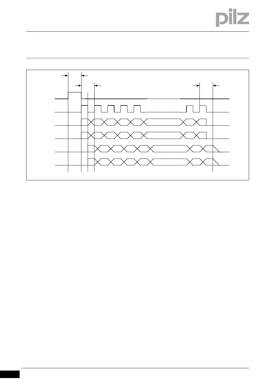
Key:
Download procedure:
IDsync
- The "IDsync" signal indicates that the download has started
- The "IDsync" signal is present for 100 ms
IDclock
- T = 100 ms
- Duty cycle = 50 %
- The "IDclock" signal is driven by the operating mode selector switch
IDo0, IDo1
- Data output;
these signal lines are used to download the Key ID number from the operating mode selec-
tor switch to the control system.
Bit 27 … Bit 14 are sent via the data line IDo0.
Bit 13 … Bit 0 are sent via the data line IDo1.
IDi0, IDi1
- Data input;
The control system uses these signal lines to confirm receipt of the previous Key ID number
(Bit 27 … Bit 0) to the operating mode selector switch.
Bit 27 … Bit 14 are received via the data line IDi0.
Bit 13 … Bit 0 are received via the data line IDi1.
(a)
The operating mode selector switch sets the "IDsync" signal, thereby signalling to the control system
that transmission is starting
(b)
A rising edge at the "IDclock" signal indicates that the data ("IDo0" and "IDo1") is present and valid and
is being read in by the control system.
(c)
The control system must output the data that was read in to lines "IDi0" and "IDi1" by the time there is
a falling edge at the "IDclock" signal.
(d)
With a rising edge at the "IDclock" signal, the operating mode selector switch reads the feedback from
the control system at IDi0 and IDi1 and checks it for equivalence.
(e)
Even at the end of the download, the control system must leave the data for at least 100 ms after the
last rising edge at the "IDclock" signal.
100 ms
IDsync
IDclock
Bit
26
Bit
27
Bit 22 … Bit 16
Bit 8 … Bit 2
IDo0
IDo1
IDi0
IDi1
(b) (c) (d)
T
(e)
100 ms
(a)
Bit
25
Bit
24
Bit
23
Bit
15
Bit
14
Bit
12
Bit
13
Bit
11
Bit
10
Bit 9
Bit 1
Bit 0
Bit
26
Bit
27
Bit 22 … Bit 16
Bit
25
Bit
24
Bit
23
Bit
15
Bit
14
Bit 8 … Bit 2
Bit
12
Bit
13
Bit
11
Bit
10
Bit 9
Bit 1
Bit 0