Altera Avalon Tri-State Conduit Components User Manual
Page 11
Chapter 2: Generic Tri-State Controller
2–5
Example Read and Write Using Setup, Hold and Wait Times
May 2011
Altera Corporation
Avalon Tri-State Conduit Components User Guide
Preliminary
Example Read and Write Using Setup, Hold and Wait Times
Figure 2–2 on page 2–6
illustrates the timing for a memory device that has
asynchronous read and write transfers, assuming a 50 MHz clock.
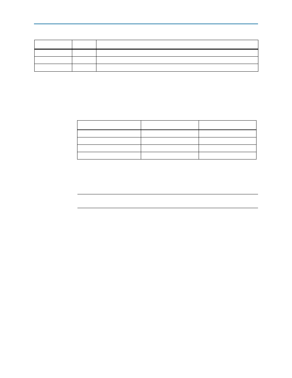
Table 2–4
lists the
parameter values set in the Generic Tri-State Controller to access this device.
When the wait time is expressed in nanoseconds, the read or write period, as seen on
the FPGA pins, is the duration of the specified wait time, rounded up to the next clock
period as
Example 2–1
illustrates.
resetrequest
On/Off
When On,
resetrequest
is asserted low and is called
resetrequest_n
.
irq
On/Off
When On,
irq
is asserted low and is called
irq_n
.
reset output
On/Off
When On,
resetoutput
is asserted low and is called
resetoutput_n
.
Table 2–3. Signal Polarities (Part 2 of 2)
Parameter
Value
Description
Table 2–4. Wait Times Expressed in Nanoseconds - 50 MHz Clock
Timing Parameter
Time in Nanoseconds
Read or Write Time
Setup wait time
50 ns
60 ns (3 clock periods)
Data hold time
10 ns
20 ns (1 clock period)
Write wait time
30 ns
40 ns (2 clock periods)
Read wait time
30 ns
40 ns (2 clock periods)
Example 2–1. Cycles When Wait Time Equals 21 ns
clock cycles = ceil(wait time in ns /clock period in ns)
clock cycles = ceil(21/20) = ceil (1.05) = 2