Byteblastermv header & plug connections – Altera ByteBlasterMV User Manual
Page 21
Advertising
Altera Corporation
2–3
ByteBlasterMV Download Cable Data Sheet
ByteBlasterMV Header & Plug Connections
The 25-pin male header connects to a parallel port with a standard parallel cable.
identifies the pins and the download modes.
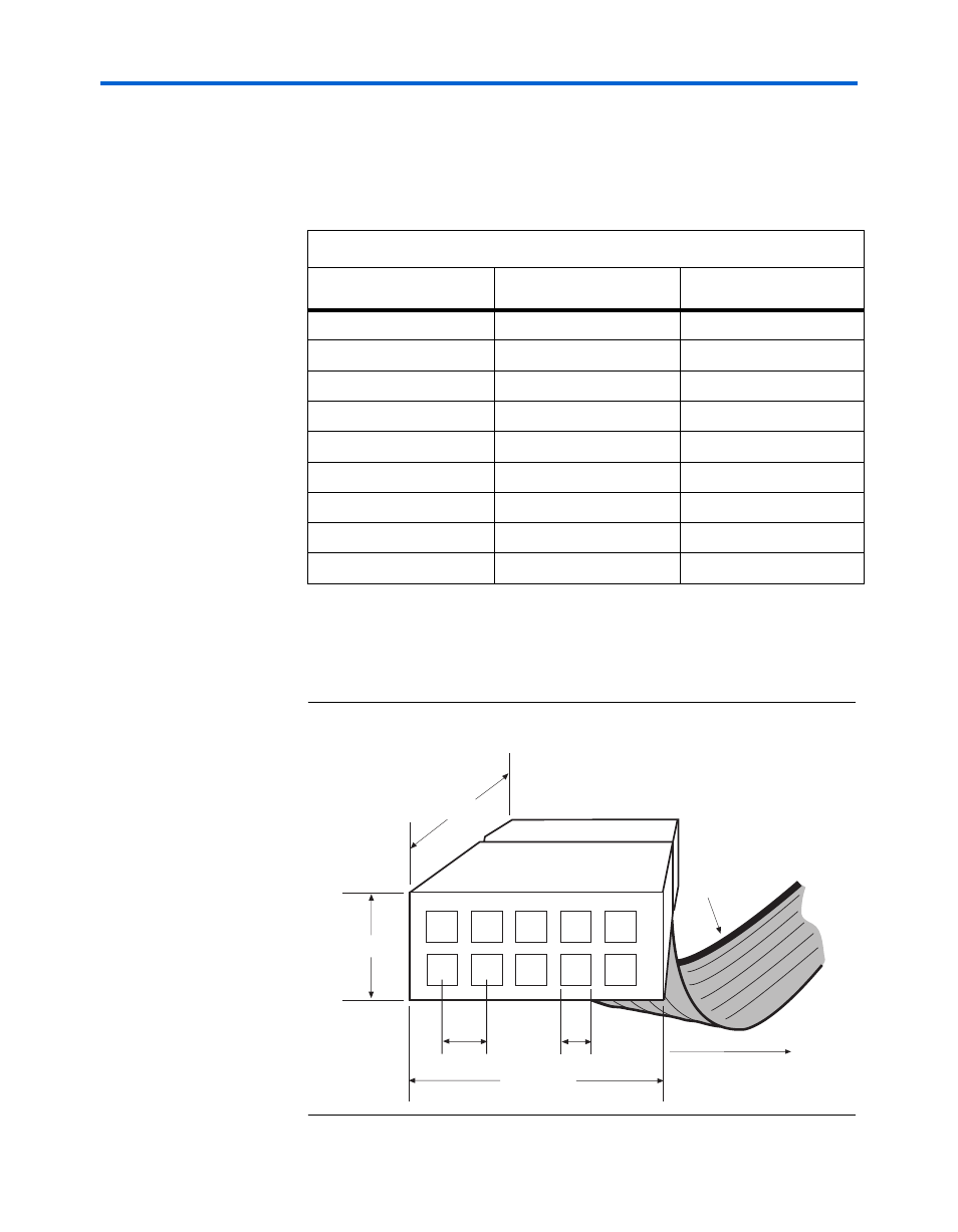
The 10-pin female plug connects to a 10-pin male header on the circuit board
containing the target device(s).
shows the dimensions of the female
plug.
Figure 2–1. ByteBlasterMV 10-Pin Female Plug Dimensions
Table 2–2. ByteBlasterMV 25-Pin Header Pin-Outs
Pin
PS Mode Signal
JTAG Mode Signal
2
DCLK
TCK
3
nCONFIG
TMS
4
—
—
5
—
—
8
DATA0
TDI
11
CONF_DONE
TDO
13
nSTATUS
–
15
nVCC Detect
nVCC detect
18 to 25
GND
GND
0.250 Typ.
0.700 Typ.
0.425 Typ.
0.100 Sq.
1
2
3
4
6
7
8
9
0.025 Sq.
Color Strip
10
5
Advertising