The configuration-status leds, Table 1–7 on – Altera Nios Development Board User Manual
Page 32
1–24
Altera
Corporation
Nios Development Board Reference Manual, Stratix Edition
September 2004
Configuration Controller Device (EPM7128AE)
1
The Nios II development kit includes the source files for the
factory-programmed reference design.
The configuration controller will stop reading data when the FPGA
successfully configures. The safe example design is setup to begin
executing code from address 0x7B0000. This region of flash memory is
factory-programmed with the web-server application software.
1
Do Not Erase
your safe hardware image (safe hardware
configuration data). If you do so inadvertently, see
Restoring the Factory Configuration
restore your board to its factory configuration.
The Configuration-Status LEDs
The EPM7128AE device is connected to four status LEDs that show the
configuration status of the board at a glance (see
). The user
can tell which configuration, if any, was loaded into the board at power-
on by looking at the LEDs (see
). If a new
configuration was downloaded into the Stratix device via JTAG, then all
of the LEDs will turn off.
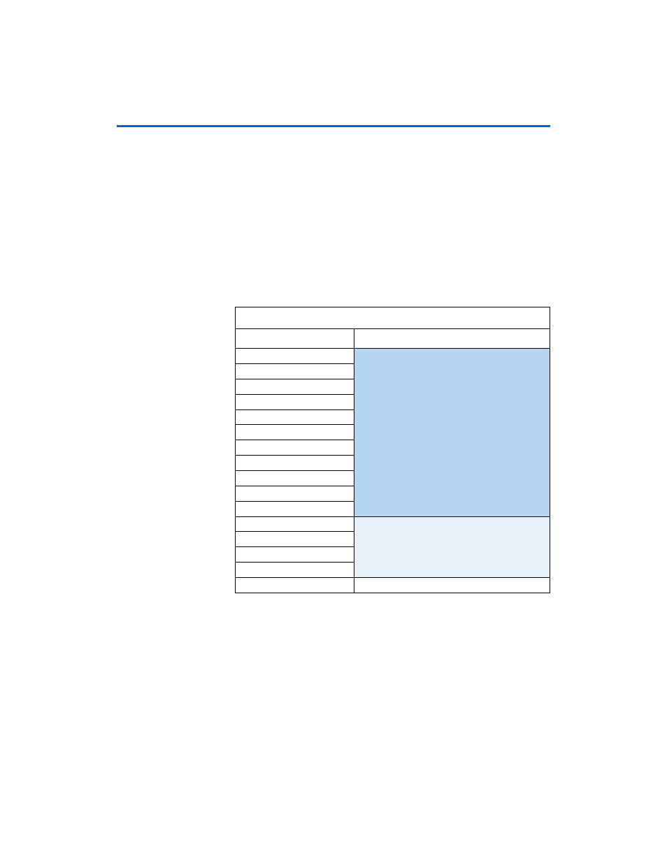
Table 1–7. Safe Hardware Configuration Data Memory Allocation
Address (hex)
Safe Hardware Image
700000
FPGA Configuration Data
710000
720000
730000
740000
750000
760000
770000
780000
790000
7A0000
7B0000
Web Server Software
7C0000
7D0000
7E0000
7F0000
Network Settings