7 rainfall sensor, Optional sensors, 1 rainfall sensor specification – Casella CEL Automatic weather station User Manual
Page 25: 2 tipping bucket - sensus channel configuration
Information
Single ended
Gain x 1
No current source
Display Format
####.#
Polynomial
Sensor specific
Enabled
Yes
Logged
Yes
Minimum Limit
800.0
Maximum Limit
1100.0
3.7
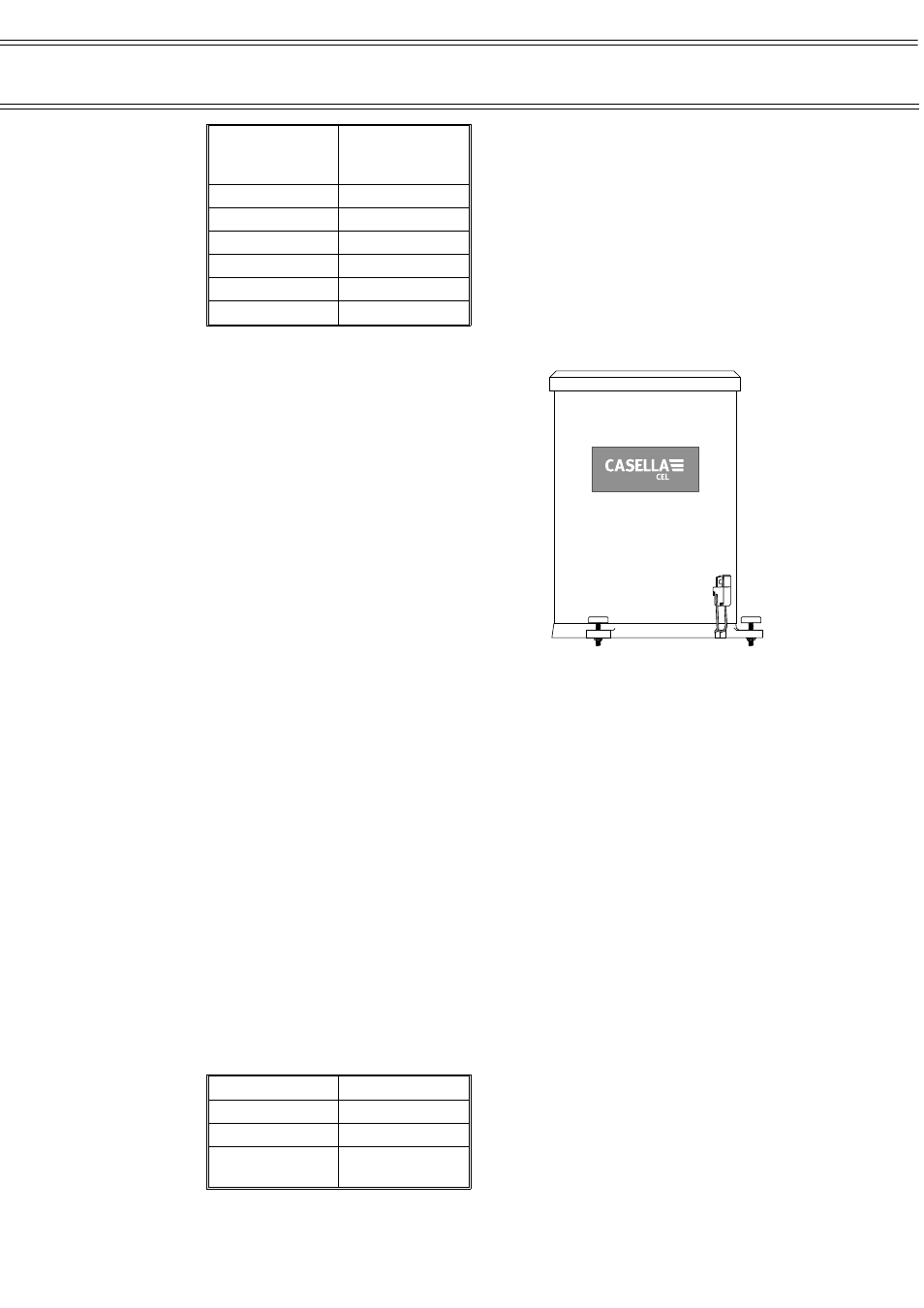
Rainfall Sensor
The tipping bucket raingauge should be
positioned horizontally at least twice the
height of any obstruction (weather station
tripod) away from the obstruction.
It is a well proven method of
monitoring rainfall with a divided bucket
assembly mounted on pivots. The bucket
assembly is adjusted to tip each time an
amount of water proportional to 0.2 mm of
rainfall has collected in one or other side of
the bucket. Therefore, each time the bucket
tips, a signal proportional to precisely 0.2 or
0.5 mm of rainfall is sent to the logger.
The gauge has a body and funnel
constructed of aluminium alloy, with an
accurately machined “Septum Ring”.
The aluminium base plate is
equipped with levelling screws and a spirit
level for precise adjustment.
3.7.1
Rainfall Sensor Specification
Part number:
100000E (0.2 mm) no de-bounce
100573E (0.5 mm) no de-bounce
Transducer:
Tipping Bucket
Aperture:
400 cm
Resolution:
0.2 or 0.5 mm per tip as relevant
Accuracy:
±1%
Capacity:
Unlimited
Operating temp:
1°C to 85°C
Supply Voltage:
7 - 20 V DC (supplied from environmental
case)
Power Consumption:
Typically 2-3 mA
Output calibration:
Debounced 0 to 5 V pulses.
Cable:
9 m cable supplied
3.7.2
Tipping Bucket - Sensus Channel Configuration
Description
Rainfall
Units
mm
Type
Counter
Information
Pulse count
Reset at midnight
Optional Sensors
02024
Tipping bucket rainfall sensor
Page 25 of 34
Automatic Weather Station
Assembly & Commissioning Handbook