CIRCUTOR CVM-NRG96 Series (Available until stocks) User Manual
Page 8
Advertising
CVM-NRG96
M9817250120-03-05A
8
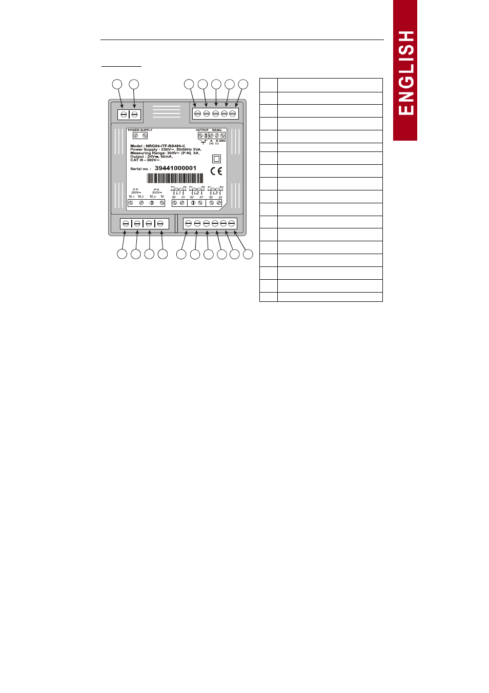
Terminal list
No. Terminal description
1
Power supply voltage input
2
Power supply voltage input
3
Transistor output RL1
4
Transistor output RL2
5
RS-485 ( + )
6
RS-485 ( - )
7
RS-485 ( GND )
8
Measurement VL1
9
Measurement VL2
10
Measurement VL3
11
Neutral measurement
12
Current input AL1 – S2
13
Current input AL1 – S1
14
Current input AL2 – S2
15
Current input AL2 – S1
16
Current input AL3 – S2
17
Current input AL3 – S1
1
3
8
12
2
5
10
14
16
7
4
9
13
6
11
15
17
Note:
Internally terminals 13, 15 and 17 are joined to terminal 6, Neutral (in no
isolated model).
The current inputs... / 5 A are isolated in model ITF.
Advertising