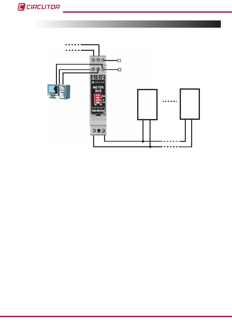
3.4.- CONNECTION DIAGRAM
AUX. Supply
24 V CC
L+
M-
MBUS-
MBUS+
B(-)
A(+)
MODBUS
Tx
Rx
RS-232
M-BUS 1
M-BUS n
MBUS-
MBUS-
MBUS+
MBUS+
GND
Figure 5:Connection diagram
Note: RS-232 communications are used to configure the unit for the first time via a PC.
10
CMBUS
Instruction Manual