Mdc-4, Mdc-4 instruction manual – CIRCUTOR MDC-4 User Manual
Page 10
Advertising
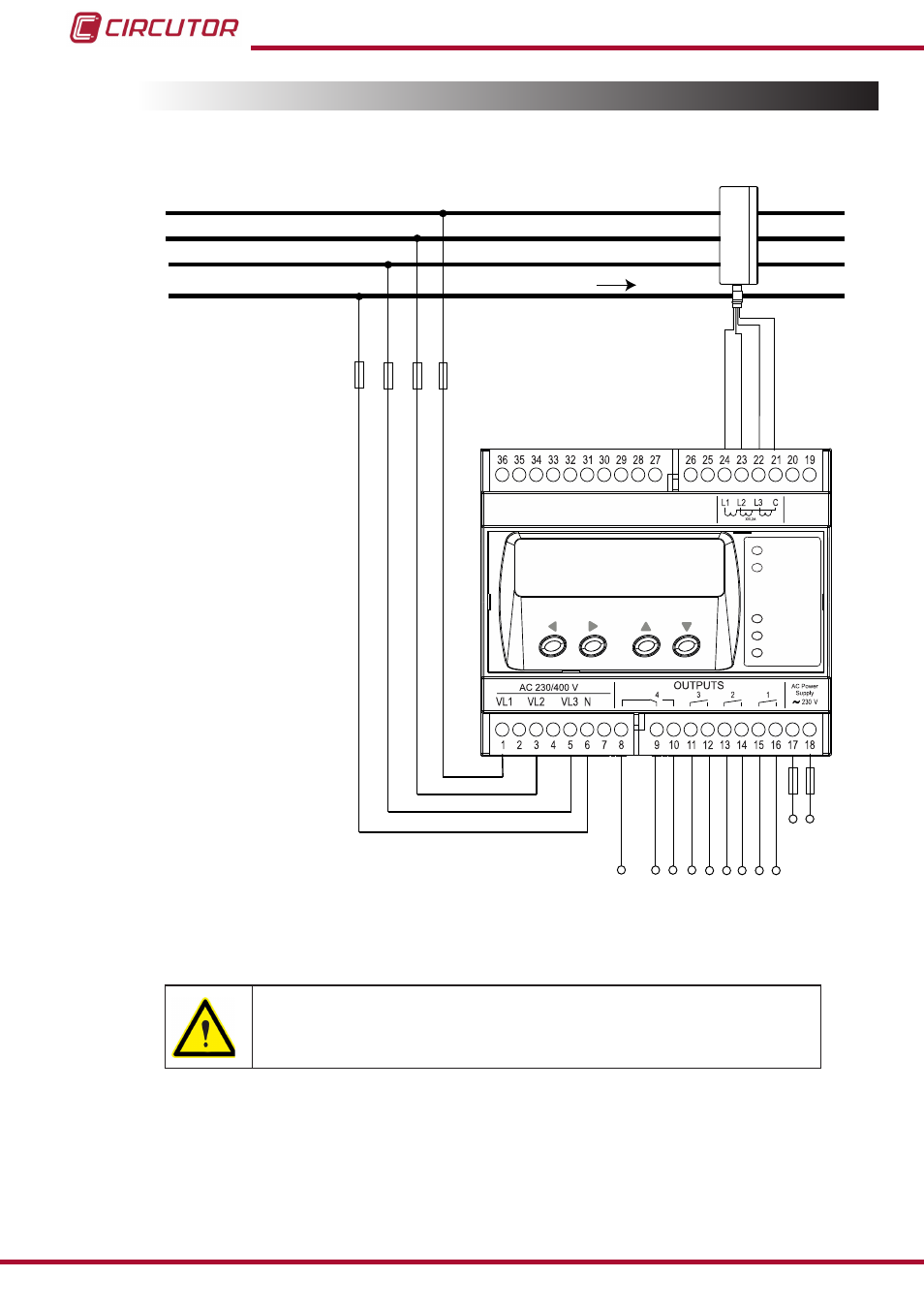
3.4.- CONNECTION DIAGRAM
3�4�1�- Three-phase network measurement with a 4-wire connection�
MDC-4
CPU
OUT 4
OUT 3
OUT 2
OUT 1
Power
Supply
V
L1
L1
L2
L3
3P1
2P1
1P1
3P2
2P2
1P2
N
V
L2
V
L3
N
LOAD
Br
own / Gr
een
Gr
ey / P
ink
Gr
een
/ W
hit
e
Red / Blue
OUT 1
OUT 2
OUT 3
OUT 4
Figure 2: Three-phase network measurement with a 4-wire connection�
The MC3 transformer secondary value is set to 0.250 A.
10
MDC-4
Instruction Manual
Advertising