Connections – CIRCUTOR CEM-C10 series User Manual
Page 11
Advertising
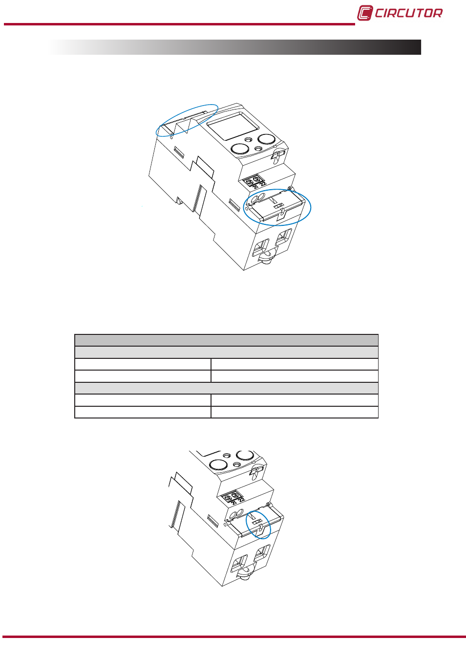
3.5.- CONNECTIONS
The
CEM-C10 has terminal covers to cover the top of the terminal box and the fixing screws
(
).
Figure 3: Terminal covers of the CEM-C10�
The fixing screws are of the mixed type, allowing the use of PZ2 and flat head screwdrivers.
Table 4:CEM-C10 connections�
Connections
Measurement terminals ( 1, 3, 4, 6)
Maximum cable cross-section
25 mm
2
( 16 mm
2
with end sleeve) ≤ 1.2 Nm
Screwdrivers head
PZ2
Impulse output terminals ( 21, 22 )
Maximum cable cross-section
1.5 mm
2
( 1.5 mm
2
with end sleeve ) ≤ 0.6 Nm
Screwdrivers head
flat head ( 3 x 0.5 mm)
Once connected, the unit can be protected with two connection seals (
Figure 4: Seal of the CEM-C10�
11
Instruction Manual
CEM-C10
Advertising