Computer, Warning – CIRCUTOR computer MAX Plug&Play series User Manual
Page 12
M98228201-03-14A
computer
MAX
6 / computer
MAX
12
- 12 -
4.2.3 Cabling cross sections and protections
The supply circuit must be protected by means of fuses or a circuit breaker sized between 0,5 and 2 A.
Recommended fuses are gl type (IEC 269) or M type (IEC 127). A main circuit breaker must be provided
in order to allow the disconnection of control circuits from supply (Computer, relays, contactor coils, etc.)
The main switch must be easily accessible. The cabling cross section must be minimum 1,5 mm
2
for the
voltage supply and for the relay outputs and 2,5 mm
2
for the cables connecting secondary of CT to
Computer
MAX
. For distances between CT and computer higher than 10m the cross section of the last
must be increased at a rate of 1 extra mm
2
every 10 m.
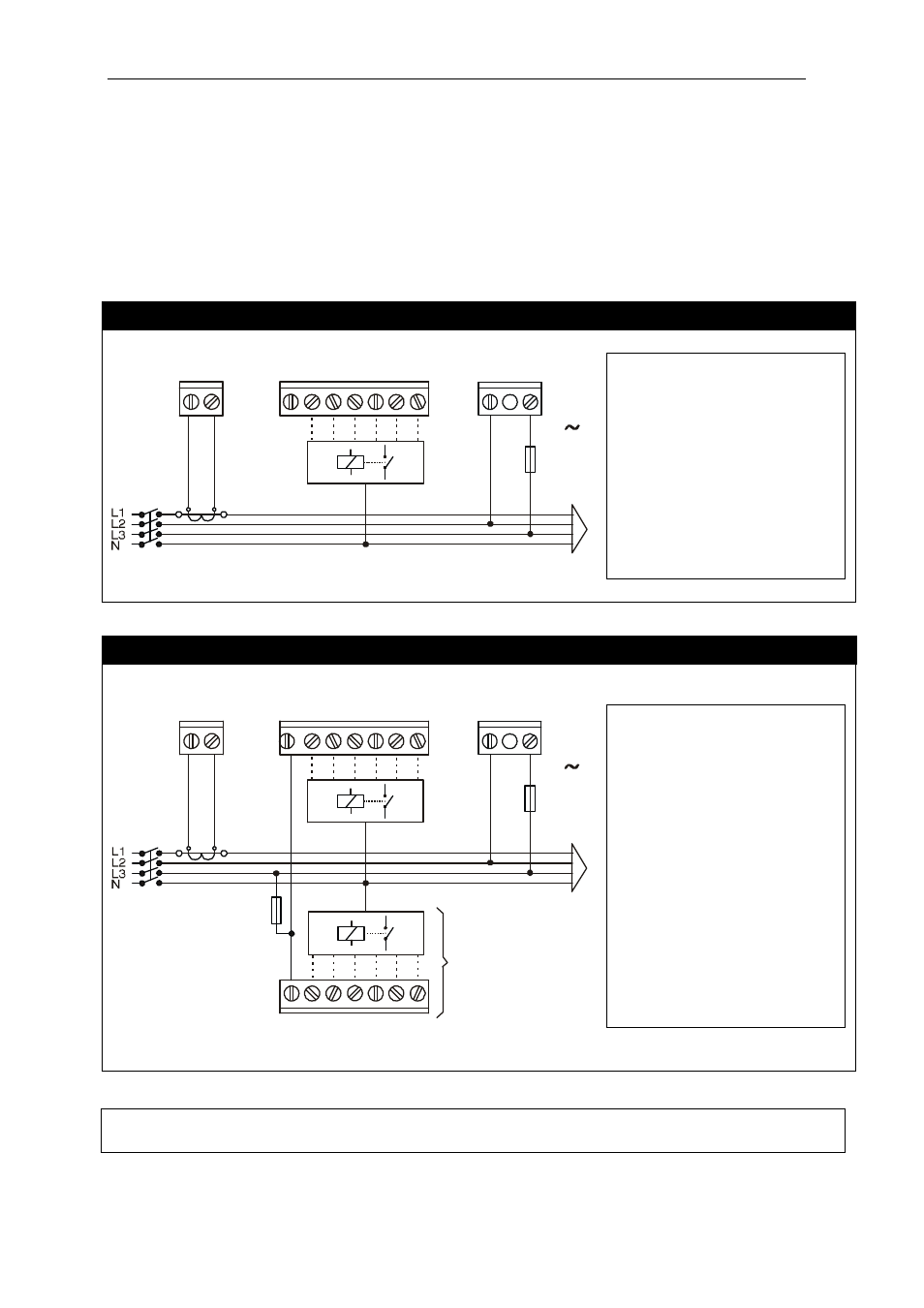
4.2.4 Schematics
computer
MAX
6
COM
0
1
2
3
4
5
6
A
B
S1
S2
C
D
RELAYS C1..C6
SUPPLY AND MEASURE
TERMINALS
V
P1
P2
Fig. 4.2.- Connection schematic for Computer
MAX
6
Nº
Terminals functions
A
Current input S1
B
Current input S2
COM Relays
common
1
Relay Output 1
2
Relay Output 2
3
Relay Output 3
4
Relay Output 4
5
Relay Output 5
6
Relay Output 6
C
Supply/Measure Input 0V
D
Supply/Measure Input(*)
(*) Rated voltage depending on type. See device label
computer
MAX
12
COM
7
8
9 10 11 12
COM
0
1
2
3
4
5
6
A
B
S1
S2
C
D
RELAYS C1..C6
RELAYS C7..C12
SUPPLY AND MEASURE
TERMINALS
V
P1
P2
Fig. 4.3.- Connection schematic for Computer
MAX
12
Nº
Terminals description
A
Current input S1
B
Current input S2
COM Relays
common
1
Relay Output 1
2
Relay Output 2
3
Relay Output 3
4
Relay Output 4
5
Relay Output 5
6
Relay Output 6
7
Relay Output 7
8
Relay Output 8
9
Relay Output 9
10
Relay Output 10
11
Relay Output 11
12
Relay Output 12
C
Supply/Measure Input 0V
D
Supply/Measure Input(*)
(*) Rated voltage depending on type. See device label
WARNING!
For Computer
MAX
12 devices (12 relay outputs) the connection between COM terminals
in the upper and lower terminal strips must be done externally.