CIRCUTOR computer MAX Plug&Play series User Manual
Page 8
M98228201-03-14A
computer
MAX
6 / computer
MAX
12
- 8 -
3.1 Display
screen
Computer
MAX
devices are equipped with a 3 digits x 7 segments LCD screen. The screen has also a
set of icons, which provide information about the regulator status. The main indications are: cosφ value,
reactive power sign (
for lagging or inductive PF and for leading or capacitive PF), connected
stages and measurement of different parameters (see section 3.2)
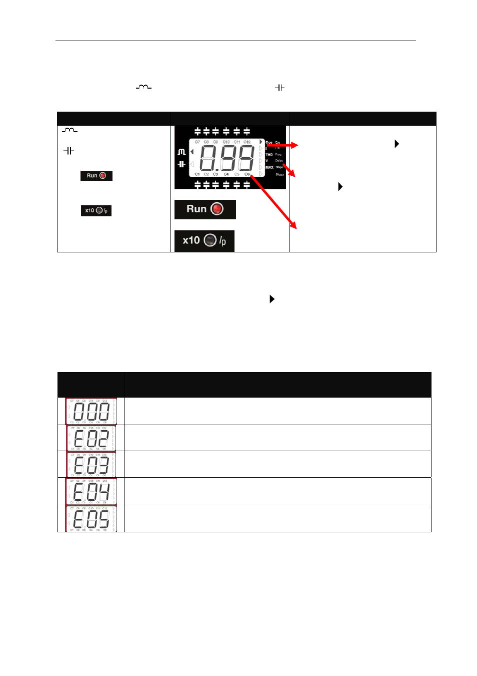
Icons
Screen and LED
Icons Indications
: Lagging or inductive
power indication
: Leading or capacitive
power indication
The
LED (red) is
ON in normal working
conditions
The
LED shows
that the reading of current or
MAX. current has to be
multiplied by 10
In normal working conditions, RUN
LED (red) is ON and cursor
points to the parameter being
displayed (Left column list)
In SET-UP mode, the RUN LED is
OFF, the cursor is blinking and
pointing to the parameter being
configured (Right column list).
Symbols indicating the stages
which are connected (only in RUN
mode)
3.2 Measured
parameters
When the instrument is in normal RUN mode, the following parameters can be displayed: cos
, mains
current, THD of both mains current and mains voltage. The instrument can also display the MAXimum
values of mains current and voltage since the last parameters clear. The parameter being displayed can
be selected with the navigation keys and is indicated by the cursor.
3.3
Errors and ERROR messages
In case that the regulator detects a possible error, the front screen shows an error code. The possible
error codes are listed and explained in table 3-1.
Table 3-1: Possible errors and messages displayed on the screen
ERROR
message
Description
Load current below the threshold current, or current transformer (CT) not
connected. The threshold is 0,1 A at the secondary side of CT
Overcompensation. The regulator detects that some stages should be
disconnected but all the stages are already disconnected.
Under-compensation. The regulator detects that some stages should be
connected and all the stages are already connected.
Overcurrent. The measured current exceeds the rated current by a + 20%.
(Rated current is considered to be the CT primary rated current)
Overvoltage. The measured voltage exceeds the rated voltage by a +15%.
3.4 Alarm
relay
In case that the number of stages configured in a Computer
MAX
6 or
MAX
12, is less than 6 or 12
respectively, the relay number 6 or 12 is automatically configured as alarm relay. The relay remains
connected in absence of alarm (positive safety) and disconnects in case that one or more of the errors
listed in section 3.2 occur. Notice that the absence of supply voltage will always be detected as an alarm
condition. The alarm relay has a delay of 10 s in case of Over-compensation and Under-compensation,
but the operation is instantaneous (delay < 1 s) in case of Over-voltage and Over-current.