CIRCUTOR computer MAX Plug&Play series User Manual
Page 13
M98228201-03-14A
computer
MAX
6 / computer
MAX
12
- 13 -
5 CONFIGURABLE
PARAMETERS
In order to adapt the regulator to the loads, certain parameters of the Computer MAX must be set-up.
The programmable parameters, the required settings and the set-up procedure are explained here below.
See also paragraph 3.5.2 to see how to select the different menu options.
The configurable parameters are listed and shortly explained below.
5.1
Plug&Play
function
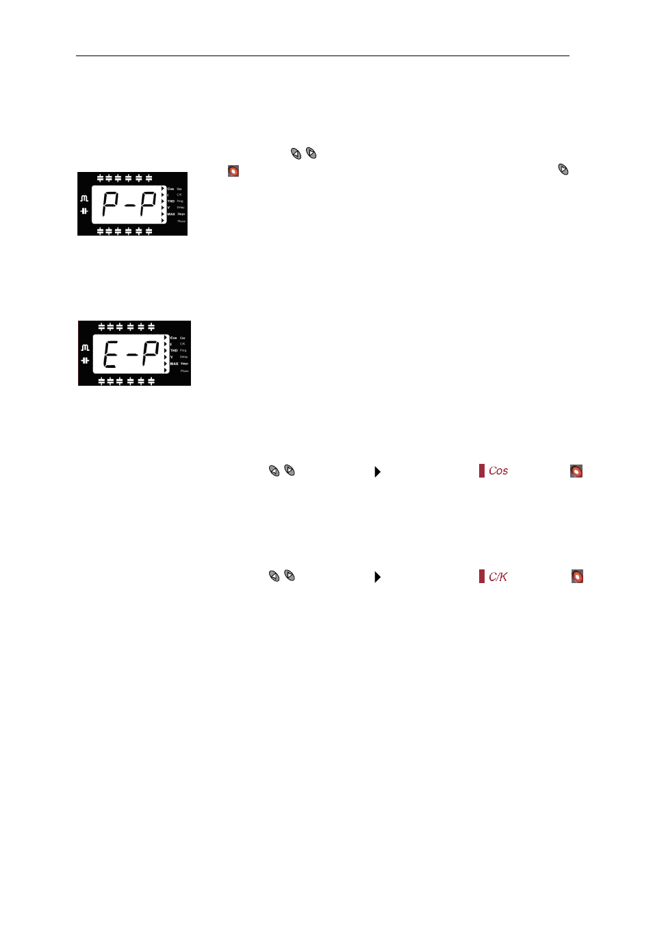
To access the Plug&Play screen, press the
buttons to open the following screen:
Press to start the process; if you want to stop the process, long press
and
it will return to its initial state.
Once started, the digits will start flashing and the unit will start a capacitor
measurement, calculation and connection and disconnection process to gather
the following capacitor bank parameters: Phase (5.8) and C/K factor (5.3).
Once the unit's Plug&Play process has finished and no error has occurred during the process, the
calculated C/K factor and the measured cosine phi will be displayed on the screen, the result of having
correctly configured the phase relationships (2 times each).
If an error occurs during the process, the following screen will appear:
Conditions for the correct operation of the Plug&Play function:
- The system should be maintained with an inductive cosine of 0.62 to 0.99
throughout the process.
- The power in the system should be stable. Any major load changes (>10 % in
less than 20 seconds) would result in an incorrect calculation of the capacitor
power ratings.
- There must be enough current in the system at the regulator's input, i.e., >100 mA AC.
- If the load is unbalanced, the correct operation of the Plug&Play function will depend on the phase to
which the current transformer is connected.
- The correct values for Program (5.5) and Number of steps (5.7) must be configured beforehand.
5.2 Target
cosφ
To set-up this parameter, use the keys
until the cursor points to the option
, then push
The parameter allows the setting of the desired PF in the installation. The regulator will control the
connection of the necessary number of capacitors to get the MAXimum approach to the target value.
Since the regulation is in a stepwise mode, the regulator will add a new step when the demanded power
is at least 70% of the lower available step power and will remove a step when the excess is also a 70% of
the lower available step power. The cosφ adjustment range is from 0,85 inductive to 0,95 capacitive.
5.3
Smaller available capacitor step
To set-up this parameter, use the keys
until the cursor points to the option
, then push
This parameter, named C/K, indicates the reactive current supplied by the smaller capacitor step,
measured at the secondary side of the current transformer (CT). Therefore, the setting value depends on
the power of the smaller capacitor step, on the CT ratio and on the supply voltage. Table 5.1 gives the
setting values of C/K for a 400 V phase to phase supply for different CT ratios and different values of
smaller capacitor step (kvar). For conditions other than those given in table 5.1, the paragraph 5.13
shows a simple calculation to obtain the C/K value. See also foot NOTE