Important – CIRCUTOR computer MAX Plug&Play series User Manual
Page 14
M98228201-03-14A
computer
MAX
6 / computer
MAX
12
- 14 -
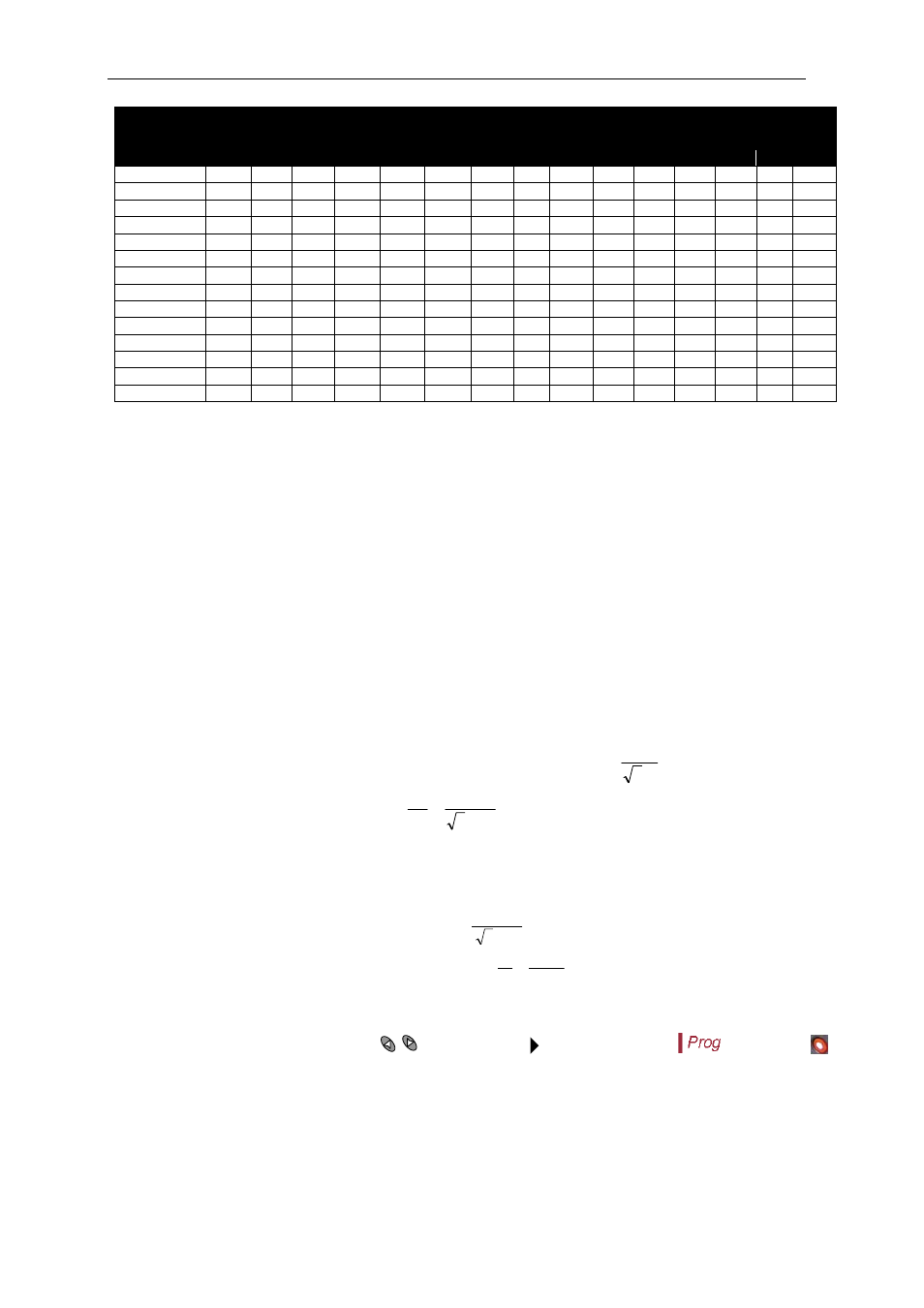
Table 5-1.- C/K factor according to smaller capacitor power and CT ratio.
CT ratio
(I
p
/I
s
)
Smaller capacitor power in kvar, at 400 V (*)
2.5
5,00
7.5
10,0
12,5
15,0
20,0 25,0 30,0
37,5 40,0 50,0 60,0 75,0 80,0
150/5
0,12
0,24
0,36
0,48
0,60
0,72
0,96
200/5
0,09
0,18
0,27
0,36
0,45
0,54
0,72
0,90
250/5
0,07
0,14
0,22
0,29
0,36
0,43
0,58
0,72
0,87
300/5
0,06
0,12
0,18
0,24
0,30
0,36
0,48
0,60
0,72
0,90
0,96
400/5
0,05 0,09
0,14 0,18 0,23
0,27
0,36
0,45
0,54
0,68
0,72 0,90
500/5
0,07
0,11
0,14
0,18
0,22
0,29
0,36
0,43
0,54
0,58 0,72 0,87
600/5
0,06
0,09
0,12
0,15
0,18
0,24
0,30
0,36
0,45
0,48 0,60 0,72 0,90
0,96
800/5
0,07
0,09
0,11
0,14
0,18
0,23
0,27
0,34
0,36 0,45 0,54 0,68
0,72
1000/5
0,05
0,07
0,09
0,11
0,14
0,18
0,22
0,27
0,29 0,36 0,43 0,54
0,58
1500/5
0,05
0,06
0,07
0,10
0,12
0,14
0,18
0,19 0,24 0,29 0,36
0,38
2000/5
0,05
0,07
0,09
0,11
0,14
0,14 0,18 0,22 0,27
0,29
2500/5
0,06
0,07
0,09
0,11
0,12 0,14 0,17 0,22
0,23
3000/5
0,05
0,06
0,07
0,09
0,10 0,12 0,14 0,18
0,19
4000/5
0,05
0,07
0,07 0,09 0,11 0,14
0,14
(*) NOTE: For supply voltages other than 400 V the C/K factor obtained from the table must be multiplied
by the ratio (400 / V
supply
)
IMPORTANT! :
If C/K is adjusted too low the system will connect and disconnect steps with a lower threshold and
therefore the number of operations to control the average PF will be higher.
If C/K is adjusted slightly above the required value (10%) the system will react with higher threshold
values and therefore the number of operations to control the average PF will be lower. Wear of PF
compensation is also lower.
5.4
C/K parameter calculation
For conditions other than those given in table 5.1 the parameter C/K can be calculated as follows.
The necessary data to perform the calculation are: The power of the smaller capacitor step, Q, the supply
voltage, V and the current transformer ratio, K
;
sec
/ I
I
K
prim
.
Where:
prim
I
is the CT primary rated current (i.e. in a 250/5 CT , the primary rated current is 250 A)
sec
I
is the CT secondary rated current , usually 5 A
Then, the smaller step reactive current, I
C
, can be calculated as:
V
.
Q
C
I
3
and the C/K parameter would be
V
.
K
.
Q
K
I
K
/
C
C
3
Example: Assume a PF equipment at 500V where the smaller capacitor is rated to 60kvar and the CT
has a ratio 500/5. The calculation would be as follows:
K ratio
100
5
/
500
K
Smaller capacitor current
A
I
C
28
,
69
500
.
3
1000
.
60
C/K parameter
69
,
0
100
28
,
69
/
K
Ic
K
C
5.5
Stage’s Configuration of PF correction equipment (Configuration program)
To set-up this parameter, use the keys
until the cursor points to the option
, then push
PF correction equipment is constituted by several capacitor stages, which may have different power
ratings. Taking as base the power of the smaller capacitor stage, the powers of the rest of stages can be
given in terms of multiples of the smaller step. Then we could state the configuration (configuration
program) of PF equipment as:
Program 1:1:1… All the stages have the same power in kvar.
Program 1:2:2… The second stage and successive have a power double than the 1st step.