5configurable parameters of the regulator – CIRCUTOR computer MAX f Series User Manual
Page 13
M066B01-03-15A
computer MAX 6f 12Vdc
- 12 -
5
CONFIGURABLE PARAMETERS OF THE REGULATOR
A series of parameters must be programmed to adjust the regulator to the installation where the cos
ϕ
will
be regulated. The programmable parameters and configuration procedure are described below. See
section 3.5.2 for selecting the different configuration options. The following parameters can be configured:
5.1
Target cos
φ
To adjust this parameter, press the
buttons until the cursor points to the option
and then
press
This parameter is used to fix the desired power factor for the installation. The regulator will add the
number of capacitors needed to adjust the value as close as possible to the target value. The regulation
process is carried out in stages so that it will not affect any switching operations until the non-
compensated demand is at least 70% of the power of the smallest stage or the excess compensation is
30% of the power of the smallest stage. Any value between 0.85 Inductive and 0.95 Capacitive can be
configured.
5.2
Current of the smallest capacitor step
To adjust this parameter, press the
buttons until the cursor points to the option
and then
press
This parameter is adjusted with the reactive current supplied by the smallest capacitor step, measured on
the current transformer's (CT) secondary. Its adjustment value will depend on the power of the smallest
capacitor step, the CT ratio and the network voltage. Table 5.1 shows the values that must be used to
adjust the C/K for a 400 V network between phases, the different transformer ratios and the power ratings
of the smallest stage. In the case of other voltages or conditions that have not been included in the table,
the C/K value can be obtained with a simple calculation, as shown in section 5.1.3
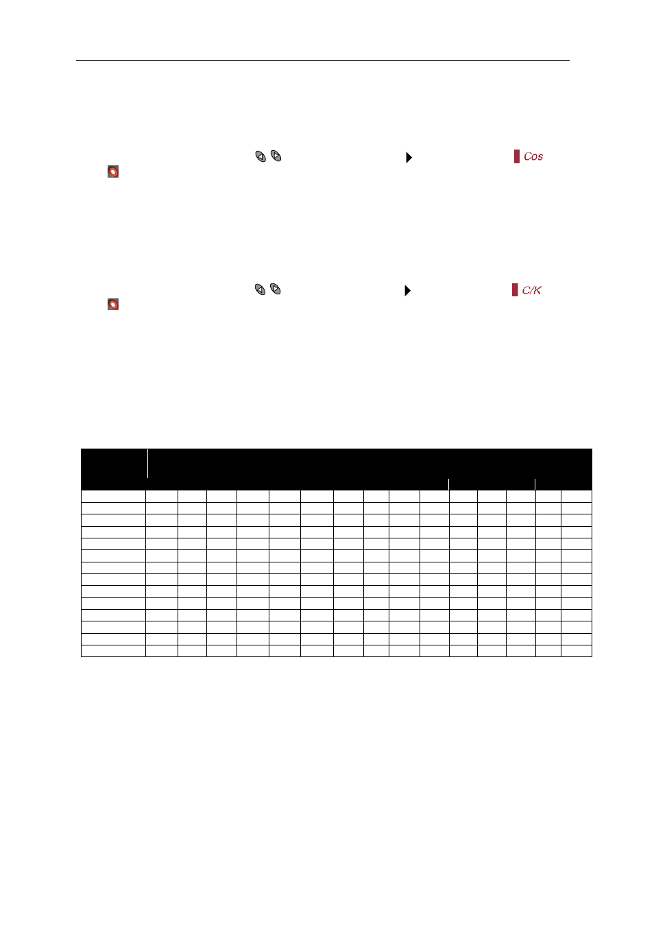
Table 5-1.- C/K Factor, in accordance with the power of the smallest stage and current transformer (CT)
ratio
CT Ratio
(
p
/I
s
)
Power in kvar of the smallest stage, in kvar, at 400 V (*)
2.5
5.00
7.5
10.0
12.5
15.0
20.0
25.0
30.0
37.5
40.0
50.0
60.0 75.0
80.0
150/5
0.12
0.24
0.36
0.48
0.60
0.72
0.96
200/5
0.09
0.18
0.27
0.36
0.45
0.54
0.72
0.90
250/5
0.07
0.14
0.22
0.29
0.36
0.43
0.58
0.72
0.87
300/5
0.06
0.12
0.18
0.24
0.30
0.36
0.48
0.60
0.72
0.90
0.96
400/5
0.05
0.09
0.14
0.18
0.23
0.24
0.36
0.48
0.58
0.67
0.72
0.87
500/5
0.07
0.11
0.14
0.18
0.22
0.29
0.36
0.45
0.54
0.54
0.72
0.87
600/5
0.06
0.09
0.12
0.15
0.18
0.24
0.30
0.36
0.45
0.48
0.60
0.72 0.90
0.96
800/5
0.07
0.09
0.11
0.14
0.18
0.23
0.27
0.33
0.36
0.45
0.54 0.68
0.72
1000/5
0.05
0.07
0.09
0.11
0.14
0.18
0.22
0.27
0.29
0.36
0.43 0.54
0.57
1500/5
0.05
0.06
0.07
0.10
0.12
0.14
0.18
0.19
0.24
0.29 0.36
0.38
2000/5
0.05
0.07
0.09
0.11
0.13
0.14
0.18
0.22 0.27
0.28
2500/5
0.06
0.07
0.09
0.10
0.12
0.14
0.17 0.22
0.23
3000/5
0.05
0.06
0.07
0.09
0.10
0.12
0.14 0.18
0.19
4000/5
0.05
0.06
0.07
0.09
0.11 0.14
0.14
(*) For other network voltages, the factor in the table, V
nom
, must be multiplied by the ratio (400/V
nom
)
IMPORTANT!:
When the C/K adjustment is too low, there will be a series of continuous connections and disconnections
with minor load variations. (The system performs more operations than those actually needed).
When the C/K adjustment is configured a little high (10%), the regulator needs demand or higher reactive
excess for switching and performs fewer switching operations.