7working mode – CIRCUTOR computer MAX f Series User Manual
Page 18
M066B01-03-15A
computer MAX 6f 12Vdc
- 17 -
7
WORKING MODE
After completing the installation and the adjustments described in the previous sections, the unit can be
set to the WORKING mode. The unit selects this mode by default after start-up and a brief moment while
the processor is initialised. Two situations could appear in said mode:
a) No alarm, Normal WORKING mode: In this case, the unit regulates the connection and
disconnection of the capacitor stages according to the needs of the installation and the screen
shows the cos
ϕ
of the installation by default. By pressing certain buttons, the different parameters
can be measured and capacitor connection or disconnection can be forced, as shown in Section
7.1.
b) Alarm mode: If any of the anomalies indicated in Section 3.2 occur, the unit shows an error code
and steps to the alarm mode. Depending on the type of error, the unit can disconnect all the
stages or continue regulating within its possibilities.
7.1
Functions of the unit in normal WORKING mode
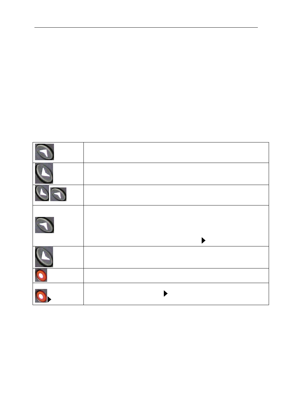
The following functions can be executed when the unit is in normal WORKING mode:
long
Manual capacitor connection: When the button is pressed down and held
(more than 1 s), the regulator begins sequentially connecting steps in time
intervals of 1 second
long
Manual capacitor disconnection If the button is held down more than 1 s, the
regulator disconnects the steps in sequence at time intervals of less than 1
second
Display of the number of connected steps: If the two buttons are pressed
simultaneously, the regulator shows the number of connected steps. Bear in mind
the difference between steps and stages (Section 1.1)
short
Parameter measurement: If a short keystroke with this button is done, a
sequence of screens are scrolled, showing the following parameters: (cos) ,
cosine
ϕ
of the installation; (I) , current; (THD), THD of the network current; (V)
Network voltage; (I, MAX) Maximum value reached by the current; (I, MAX)
maximum value reached by the voltage;.
The parameter displayed is indicated with the cursor
short
Parameter measurement: Scrolls through the same parameters indicated in the
previous panel, but in reverse order
long
Keypad for entering the configuration mode: After a long keystroke of this
button (more than 1 s) the unit changes to the configuration mode
MAX
Button for erasing maximums: If a long keystroke is done with this button
(more than 1 sec) when the cursor marks MAX, the unit resets the maximum
values of I and V registered while operating.