CIRCUTOR computer MAX f Series User Manual
Page 8
M066B01-03-15A
computer MAX 6f 12Vdc
- 7 -
3.1
Screen
The regulator screen is a three-digit LCD with seven segments. It also has several icons that provide
information about the regulator state, such as indicating the value of the cos
φ
, the reactive power sign
(inductive
or capacitive
), signals for the connected stages, and various parameter measures (see
section 3.2)
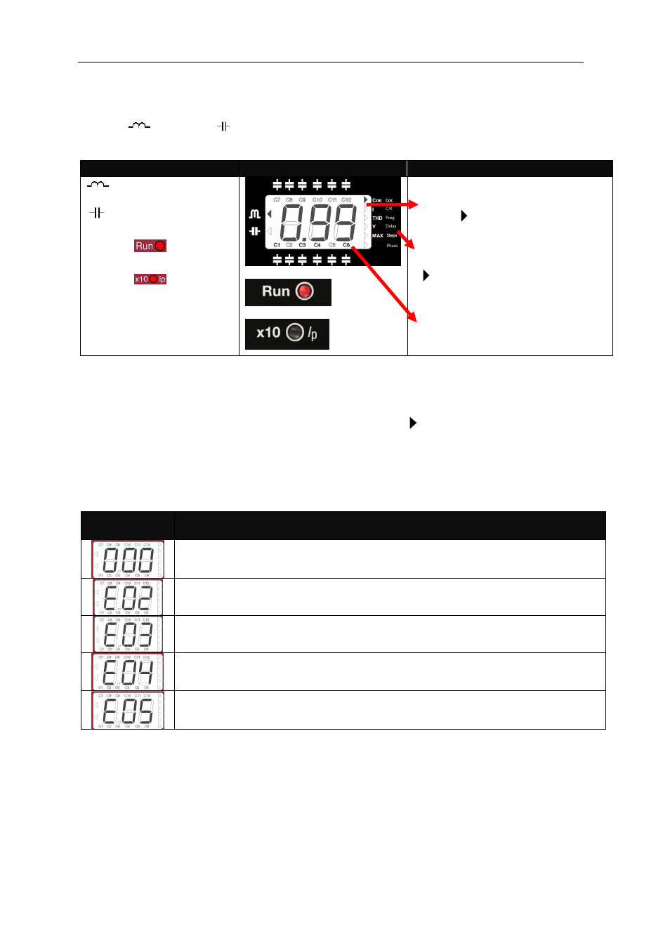
Icons
Screen and LEDs
Indicating Icons
Inductive reactive power
Capacitive reactive power
The LED
(red) lights
up during normal operation
The LED
shows that
current I or the Imax shown
on the display must be
multiplied by 10
In the NORMAL or WORKING
mode, the RUN LED is lit and the
cursor
indicates the parameter
being measured (Left list)
In the CONFIGURATION mode,
the RUN LED is off and the cursor
is
blinking,
indicating
the
parameter being adjusted (Right
list).
Symbols indicating the connected
capacitors
(only
in
NORMAL
mode)
3.2
Parameter measurement
During the normal operating mode, the regulator measures the following parameters: cos
ϕ
, mains
current, THD of the network current and network voltage. The section also shows the maximum values of
the current and network voltage from the previous parameter reset. The measured parameter can be
changed with the navigation arrows and is indicated by the cursor
3.3
Errors and ERROR Messages
If the unit detects and error, a code appears on the screen indicating the type of error detected. The
errors that can be detected and the messages displayed on the screen are summarised in Table 3.1.
Table 3-1: Errors and messages displayed on the screen
ERROR
message
Description
Load current below minimum or current transformer not connected. Appears if
Isec<0.05 A
Overcompensation. A disconnect request is made and all the stages are
disconnected.
Undercompensation. A connection request is made and all the stages are
connected.
Overcurrent. The current measured exceeds the nominal current by + 20 %. The
nominal current is considered to be that of the CT primary
Overvoltage. The measured rated voltage exceeds the nominal voltage by 15 %
or more..