Installation location – CIRCUTOR OPTIM-EMS-C Series User Manual
Page 12
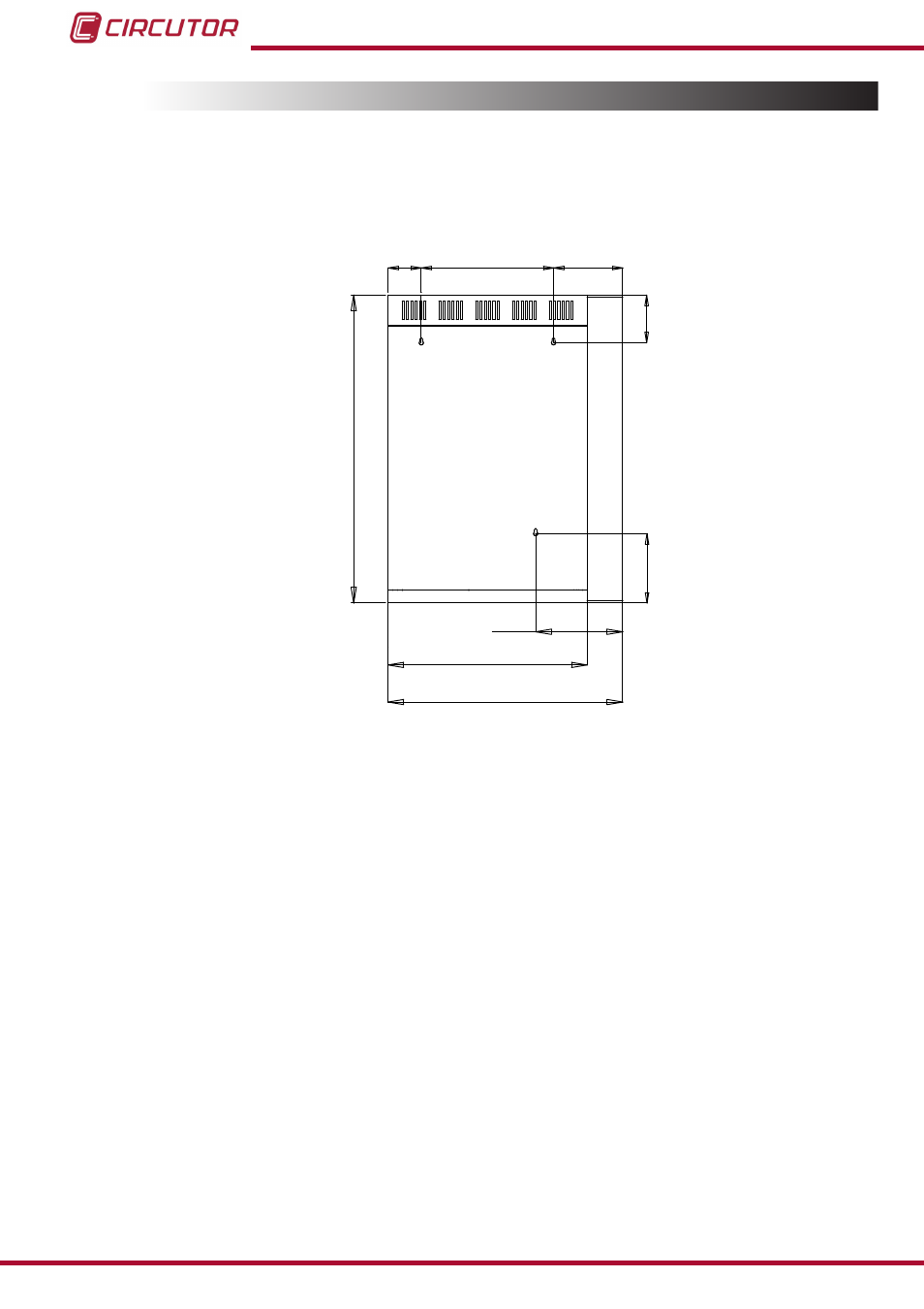
3.3.- INSTALLATION LOCATION
It is important to maintain a minimum distance around the unit to facilitate cooling.
As it is a wall-assembled cabinet, use the three 10 mm diameter holes made in the rear of the
cabinet for wall mounting, as shown in
, use suitable fixing elements for supporting its
weight.
460
710
542.7
110
76.7
306
160
160
200
Figure 5: Points for fixing OPTIM EMS-C capacitor banks to the wall.
In self-supporting cabinets, the back and front sides of the cabinet must be kept at least
60 cm
away from walls of other units and infrastructures to allow for ventilation.
As regards side walls, it is recommended leaving at least a
20 cm separation between adjacent
cabinets.
Note: Static units have an aluminium heatsink to cool the thyristors. Periodically clean these
heatsinks with a brush or with compressed air and ensure that they have maximum ventilation.
Make sure the unit can be accessed easily.
The environmental conditions of the location where the unit is installed must not exceed the
limits set forth in the technical features (See
To ensure proper ventilation, the unit must be installed in a vertical position.
In accordance with the LVR, once the unit is installed, the installation must be protected against
direct and indirect contacts. Therefore, a circuit breaker and earth leakage protection for the
capacitor bank power supply line should be installed.
12
OPTIM EMS-C series
Instruction Manual