CIRCUTOR OPTIM-EMS-C Series User Manual
Page 18
2.- Connect the power supply to the panel and check that the regulator display illuminates im-
mediately.
Otherwise, stop and check the previous step.
3.- Check the regulator's cos φ indication.
If the indication is out of the 0.5 to 1 range, it may be possible that the current transformer and
/ or the power supply to the regulator are improperly connected.
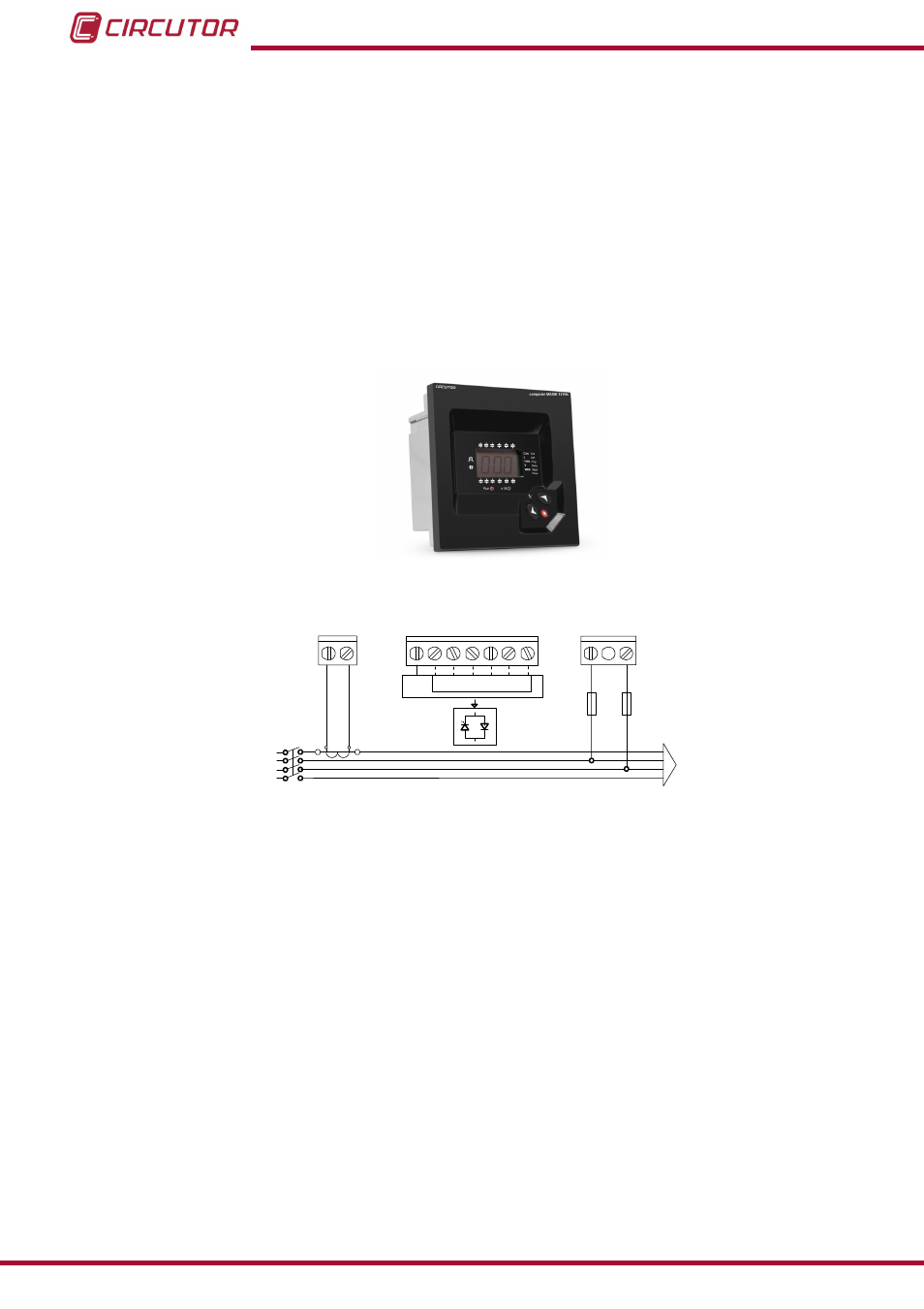
The
Computer Max 6f 12Vdc regulator (
) uses a single current transformer.
Its connection is made as shown in
(we recommend connecting the current transform-
er on phase L1 and drawing the voltage power supply from phases L2 and L3).
Figure 12: Computer Max Regulator (Photo for illustrative purposes, the model used in your unit may differ).
-
+ C1 ... C6
-
L1
L2
L3
N
POWER
SUPPLY
0
1 2 3 4 5 6
400 V ac
A B
P1
P2
S1
S2
C
D
Figure 13: Computer Max regulator connection.
4.- Once ensured that the regulator is properly connected, adjust the regulator parameters for
the installation you are attempting to compensate.
For this, follow the instructions in the regulator manual or quick guide that comes with the ca-
pacitor bank.
18
OPTIM EMS-C series
Instruction Manual