External isolation and protection elements, Auxiliary control voltage, Earth cable connection – CIRCUTOR OPTIM-EMS-C Series User Manual
Page 14
3.6.- EXTERNAL ISOLATION AND PROTECTION ELEMENTS
The capacitor bank has a manual internal four-pole isolator, but it must be connected to a line
that is protected by a circuit breaker as well as earth leakage protection at the header, in ac-
cordance with Spanish Low-Voltage Electrotechnical Regulations (LVR) and depending on the
earthing system of the installation.
The protection elements, isolation switches and/or switches that are added exter-
nally to the capacitor bank must be of a minimum size to withstand a current 1.5
times greater than what is indicated on the label (LVR, ICT-BT-48)
If an earth leakage protection for the capacitor bank is installed, its sensitivity and
trip delay must be adjustable.
For capacitor banks equipped with a standard regulator that measures the current in a single
phase, we advise installing the current transformer (CT) in the phase connected to L1 (black
cable).
The CT S1 and S2 outputs must be connected to the terminals with the same name on the
capacitor bank.
For more details about the CT connection, see
3.9.- CURRENT TRANSFORMER (CT)
3.7.- AUXILIARY CONTROL VOLTAGE
The standard model of the
OPTIM EMS-C capacitor banks does not require auxiliary voltage
for control or operation.
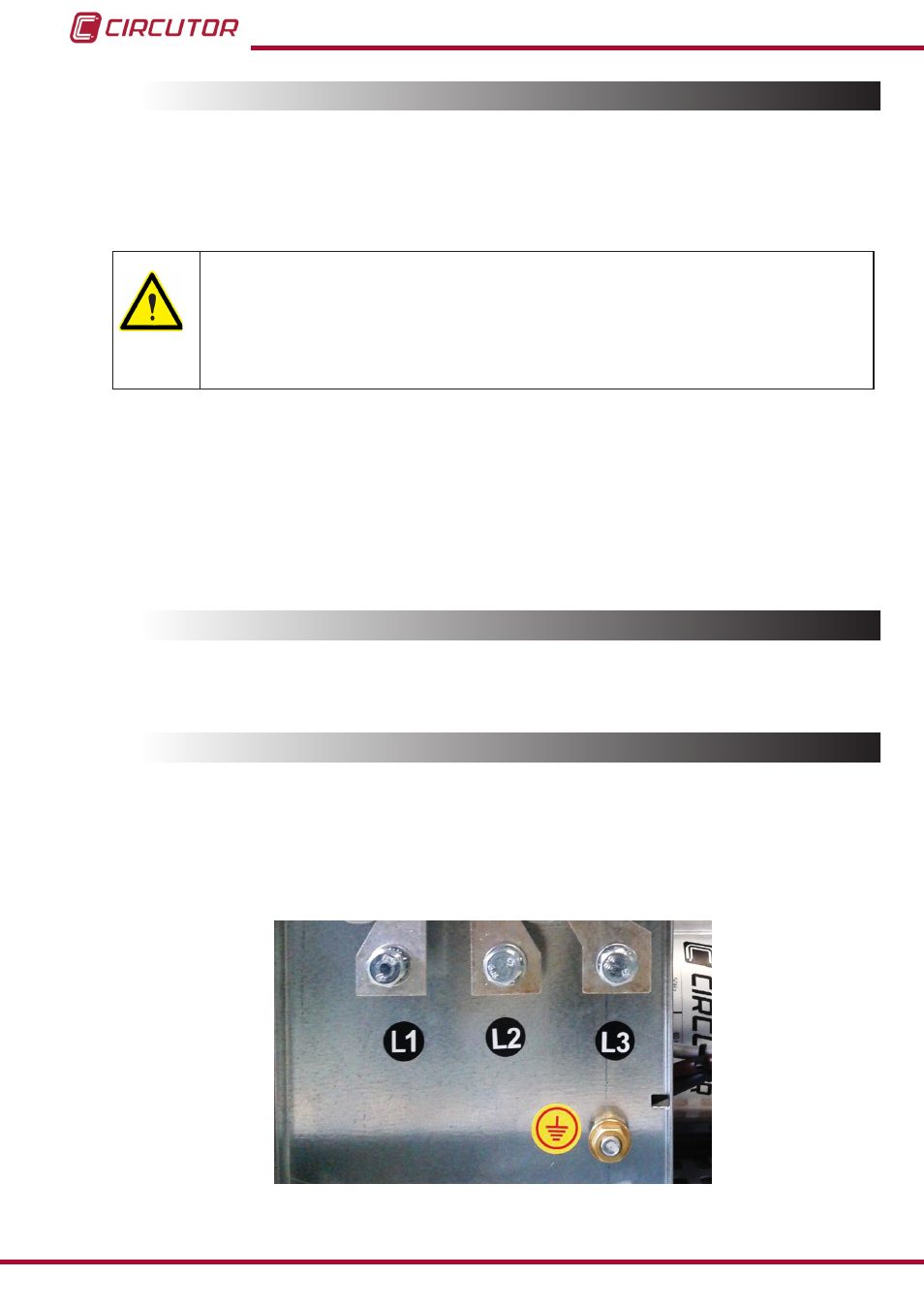
3.8.- EARTH CABLE CONNECTION
Connect the earth terminal of the capacitor bank housed inside the operations panel of the
unit (see (
) to the exterior earth connection.
The earth cable cross-section must be selected in accordance with the admissible current
limits established in the LVR (ITC-BT-19 – Indoor or receiver installations).
Figure 7: Earth terminal for the connection to the external earth of the OPTIM EMS-C capacitor banks.
14
OPTIM EMS-C series
Instruction Manual