7 bi-directional data transmitter – KBC Networks 3U Chassis Transceiver User Manual
Page 18
Manual-FD_BSeries-Rev1008.pdf Page 14 of 34
Copyright © KBC Networks Ltd.
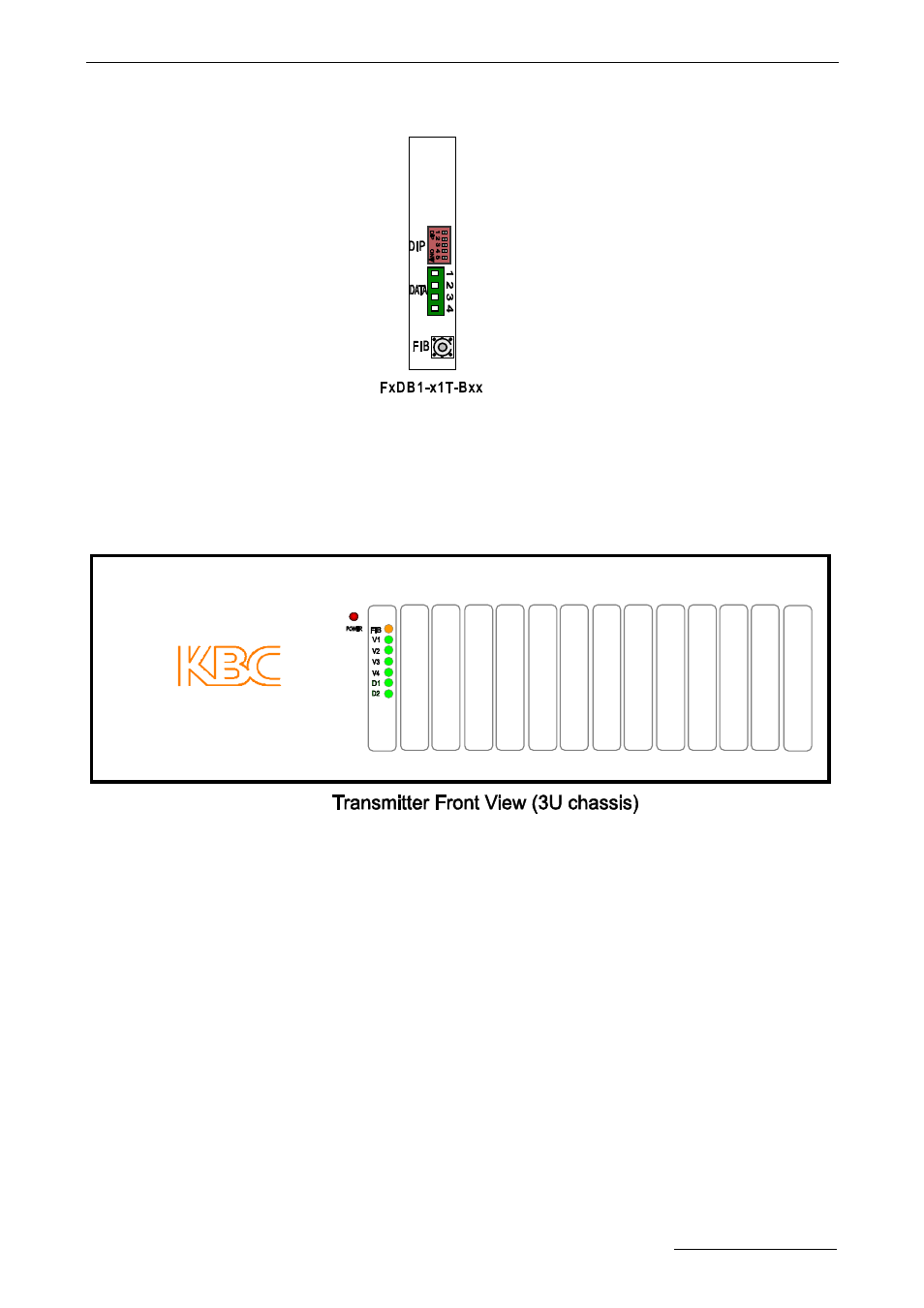
3.7 Bi-directional Data Transmitter
Connectors:
FIB: Fiber Optic.
DATA: RS232/RS422/2 wires RS485 or 4 wires RS485 compatible, Terminal. Terminal
pins assignment and DIP Switch setting refer to Table 1 and Table2 in section 5.
Data Block Connections and DIP Switch Setting.
LEDs Definition:
POWER: Power Supply. On if power input is OK.
Off if no power present.
FIB: Fiber Link. Off if link continuity is good.
On if no link continuity.
V1-V4: Video. Not used.
D1: RS232/RS422/ 4 wires RS485 Transmit Data.
:
Flash if data being transmitted.
Off if no data being transmitted.
2 wires RS485 Transmit/ Receive Data. Flash if there is activity.
D2: RS232/RS422/ 4 wires RS485 Receive Data. Flash if data being received.
Off if no data being received.
2 wires RS485 Transmit/ Receive Data. Not used.