KBC Networks 3U Chassis Transceiver User Manual
Page 28
Manual-FD_BSeries-Rev1008.pdf Page 24 of 34
Copyright © KBC Networks Ltd.
FIB: Fiber Optic.
V:
Video Output, BNC.
DATA: RS232/RS422/2 wires RS485 or 4 wires RS485 compatible. Terminal pins
assignment and DIP Switch setting refer to Table 1 and Table2 in section 5.
Data Block Connections and DIP Switch Setting.
C1: Contact Closure, input.
C2:
Contact Closure, output. The Contact Closure state, Open or Close, of the
contact closure on the receiver end follows the state of the contact closure on
the transmitter end. I.e. if the contact on the transmitter end are Close, the
contact on the receiver end is made to be Close. If the contact on the
transmitter end is Open, the contact on the receiver end is made to be Open.
Terminal pins assignment as below:
Contact Closure input
“A”
Contact Closure input
“B”
Contact Closure output
“A”
Contact Closure output
“B”
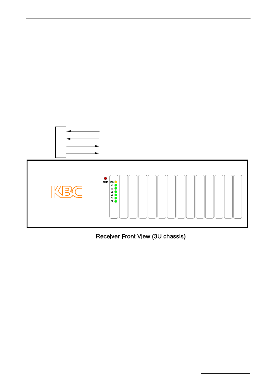
LEDs Definition:
POWER: Power Supply. On if power input is OK.
Off if no power present.
FIB: Fiber Link. Off if link continuity is good.
On if no link continuity.
V1:
;
Video.
On if video output is OK.
Off if no video present.
V2-V4: Video. Not used.
D1:
RS232/RS422/ 4 wires RS485 Transmit Data.
:
Flash if data being transmitted.
Off if no data being transmitted.
2 wires RS485 Transmit/ Receive Data. Flash if there is activity.
D2: RS232/RS422/ 4 wires RS485 Receive Data. Flash if data being received.
Off if no data being received.
2 wires RS485 Transmit/ Receive Data. Not used.
1
2
3
4