Data block connection and dip switch setting – KBC Networks 3U Chassis Transceiver User Manual
Page 31
Manual-FD_BSeries-Rev1008.pdf Page 27 of 34
Copyright © KBC Networks Ltd.
Off if no data being transmitted.
2 wires RS485 Transmit/ Receive Data. Flash if there is activity.
D2: RS232/RS422/ 4 wires RS485 Receive Data. Flash if data being received.
Off if no data being received.
2 wires RS485 Transmit/ Receive Data. Not used.
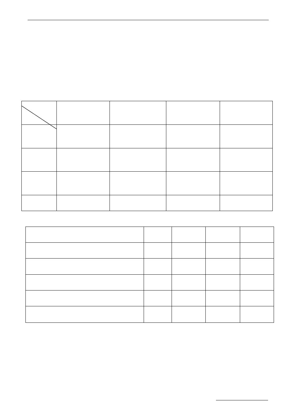
5. Data Block Connection and DIP Switch Setting
Table 1:
Table 2:
DIP Switch pin name
RS-232
RS-422
4wire
RS-485
2wire
RS-485
D1( RS422/4 wires RS485 input terminator
120
Ω )
OFF
ON/OFF
②
ON/OFF
②
OFF
D2( 2 wires RS485, RS422 or 4 wires RS485
output terminator 120
Ω )
OFF
ON/OFF
②
ON/OFF
②
ON/OFF
②
D3( 2 wires RS485 or 4 wires RS485 output
Pull-up/Pull-down resistance )
OFF
OFF
ON/OFF
①
ON/OFF
①
D4( RS232/RS422/2 wires RS485 or 4 wires
RS485 select )
OFF
OFF
ON
ON
D5( RS232/RS422/2 wires RS485 or 4 wires
RS485 select )
ON
OFF
OFF
ON
①
The 2 wires RS485 OR 4 wires RS485 output bus pull-up and pull-down resistance usually should be
switched on. But if there are several fiber transmitters or receivers, 2 wires RS485 or 4 wires RS485
output interfaces are connected together, only one of the 2 wires RS485 or 4 wires RS485 output
Pull-up and Pull-down resistance should be switched on, the others should be switched off.
②
The terminators can be switched on or off according to the RS485 bus connection. When the fiber
transmitter or receiver is placed at the end point of bus, the terminators are usually switched on, but
not be must, so the same as RS422.
Pin Name
Data
1
2
3
4
RS232
TXD
Data transmit signal;
input
RXD
Data receive signal;
output
GND
GND of RS232 data
NC
(not connected)
RS422
TXD+
Data transmit signal
“+”, input
TXD-
Data transmit signal
“−”, input
RXD+
Data receive signal
“+”, output
RXD-
Data receive signal
“−”, output
4 wires
RS485
485 TX+
Data transmit signal
“+”, input
485TX-
Data transmit signal
“−”, input
485RX+
Data receive signal
“+”, output
485RX-
Data receive signal
“−”, output
2 wires
RS485
NC
(not connected)
NC
(not connected)
485+
Data signal
“+”
485-
Data signal
“−”