Analog Way PULSE LE - Ref. PLS200 Programmer's Guide User Manual
Page 49
49
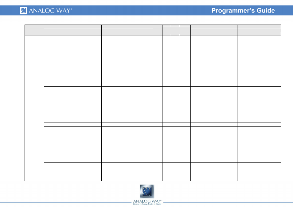
Group
Name
CmdResp Description
Read
/
Write
Min
Value
Max
value
Default
value
Values
Index #1
Index #2
AUDIO
AUDIO_INPUT_MODE
Af
Af
Audio mode
Rd/Wr0
1
1
0 = Free choice of audio input
1 = Audio input follow the top
layers
AUDIO_INPUT_MAP
Ai
Ai
Audio input map
Rd/Wr0
12
1
0 = No input
1 = Input1
2 = Input2
3 = Input3
4 = Input4
5 = Input5
6 = Input6
9 = Input9
10 = Input10
11 = Input11
12 = Input12
0 = Input1
1 = Input2
2 = Input3
3 = Input4
4 = Input5
5 = Input6
8 = Input9
9 = Input10
10 = Input11
11 = Input12
AUDIO_LEVEL
AL AL
Audio input level
Rd/Wr0
255 45
Linear scale, init value is 0 dB
0 = Input1
1 = Input2
2 = Input3
3 = Input4
4 = Input5
5 = Input6
8 = Input9
9 = Input10
10 = Input11
11 = Input12
AUDIO_AUX_LEVEL
Al
Al
Audio auxiliary input level
Rd/Wr0
255 45
Linear scale, init value is 0 dB
AUDIO_BALANCE
Ab Ab
Audio input balance
Rd/Wr0
90
45
0 = max to the left, 45 =
centered, 90 = max to the right
0 = Input1
1 = Input2
2 = Input3
3 = Input4
4 = Input5
5 = Input6
8 = Input9
9 = Input10
10 = Input11
11 = Input12
AUDIO_AUX_BALANCE
AB AB Audio auxiliary input balance
Rd/Wr0
90
45
0 = max to the left, 45 =
centered, 90 = max to the right
AUDIO_MUTE
Au Au
Audio output Mute control
Rd/Wr0
1
0
1 = Mute.
0 = Main output
1 = Preview
output