3 front panel, 1 reset/abort switch, Figure 3-2 – Artesyn MVME7100 Single Board Computer Installation and Use (June 2014) User Manual
Page 51: Front panel leds, connectors, switch, Controls, leds, and connectors
Advertising
Controls, LEDs, and Connectors
MVME7100 Single Board Computer Installation and Use (6806800E08D)
51
3.3
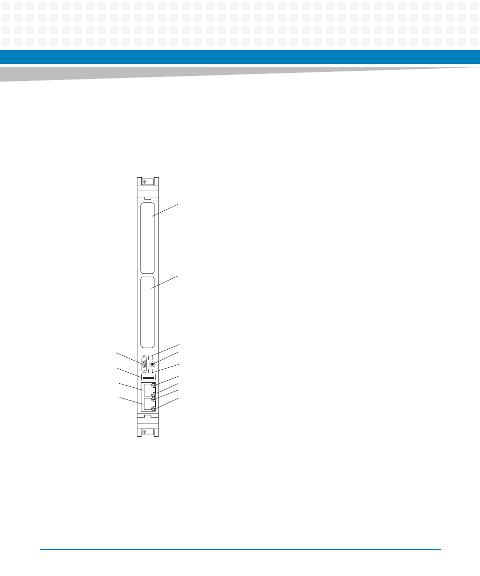
Front Panel
The following switch, LEDs, and connectors are available on the MVME7100 front panel. Refer
to
for the location of each.
3.3.1
Reset/Abort Switch
The MVME7100 has a single push button switch to provide both the abort and reset functions.
When the switch is depressed for less than 3 seconds, an abort interrupt is generated to the
MC8641D PIC. If the switch is held for more than 3 seconds, a board hard reset is generated. If
the MVME7100 is the VMEbus system controller, a VME SYSRESET is generated.
Figure 3-2
Front Panel LEDs, Connectors, Switch
PMC 1
PMC 2
GENET 2
ABT/RST
SPEED
ACT
GENET 1
SPEED
ACT
USER 1
FAIL
COMM 1
USB
Advertising