7 vmebus p2 connector, Table 3-15, Vme p2 connector pinouts – Artesyn MVME7100 Single Board Computer Installation and Use (June 2014) User Manual
Page 68: Controls, leds, and connectors
Controls, LEDs, and Connectors
MVME7100 Single Board Computer Installation and Use (6806800E08D)
68
3.3.3.7
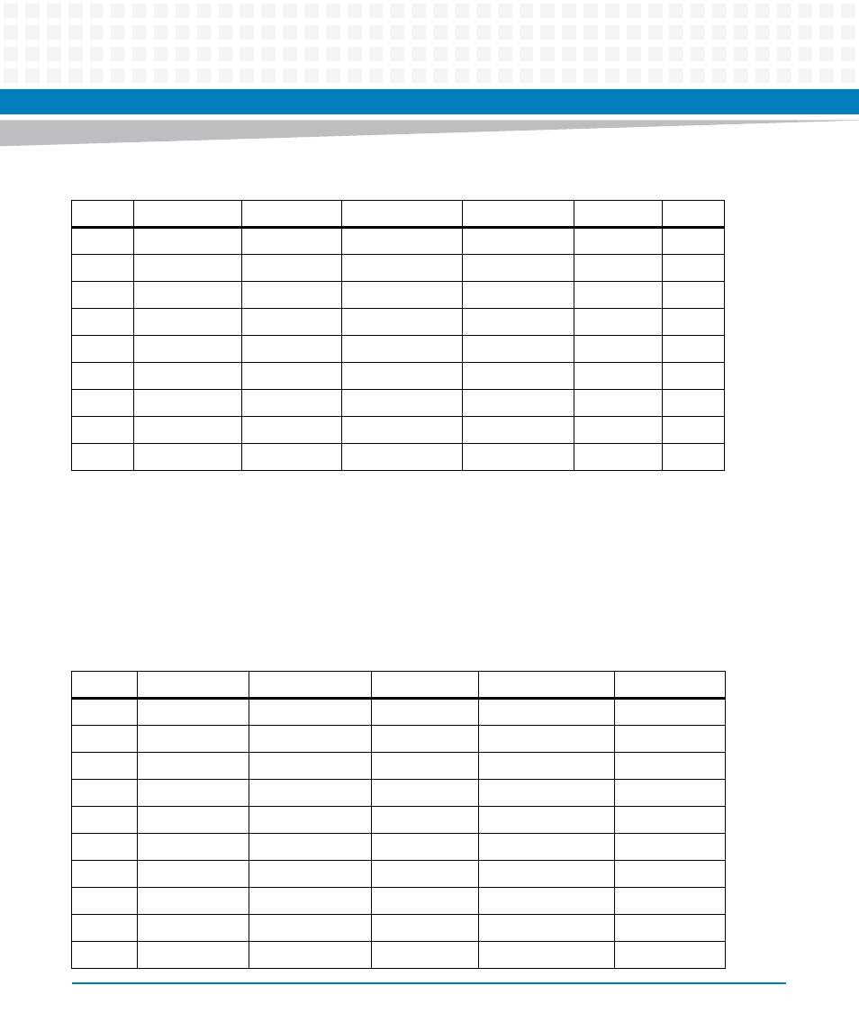
VMEbus P2 Connector
The VME P2 connector is a 160-pin DIN. Row B of the P2 connector provides power to the
MVME7100 and to the upper eight VMEbus address lines and additional 16 VMEbus data lines.
The Z, A, C, and D pin assignments for the P2 connector are the same for both the MVME7100
and MVME7216E, and are as follows:
24
GND
A07
IRQ7*
A14
Reserved
24
25
Reserved
A06
IRQ6*
A13
Reserved
25
26
GND
A05
IRQ5*
A12
Reserved
26
27
Reserved
A04
IRQ4*
A11
Reserved
27
28
GND
A03
IRQ3*
A10
Reserved
28
29
Reserved
A02
IRQ2*
A09
Reserved
29
30
GND
A01
IRQ1*
A08
Reserved
30
31
Reserved
-12V
+5VSTDBY
+12V
GND
31
32
GND
+5V
+5V
+5V
+5V
32
Table 3-14 VMEbus P1 Connector Pin Assignments (continued)
ROW Z
ROW A
ROW B
ROW C
ROW D
Table 3-15 VME P2 Connector Pinouts
Pin
P2-Z
P2-A
P2-B
P2-C
P2-D
1
SP1RX
PMC1_IO2
+5V
PMC1_IO1
E1-1+
2
GND
PMC1_IO4
GND
PMC1_IO3
E1-1-
3
SPITX
PMC1_IO6
VRETRY_L
PMC1_IO5
GND
4
GND
PMC1_IO8
VA24
PMC1_IO7
E1-2+
5
SP1CTS
PMC1_IO10
VA25
PMC1_IO9
E1-2-
6
GND
PMC1_IO12
VA26
PMC1_IO11
GND
7
SP1RTS
PMC1_IO14
VA27
PMC1_IO13
E1-3+
8
GND
PMC1_IO16
VA28
PMC1_IO15
E1-3-
9
SP2RX
PMC1_IO18
VA29
PMC1_IO17
GND
10
GND
PMC1_IO20
VA30
PMC1_IO19
E1-4+