4 serial port connector (com1/j1), 5 usb connector (j2), Table 3-12 – Artesyn MVME7100 Single Board Computer Installation and Use (June 2014) User Manual
Page 66: Com1 port connector pin assignments, Table 3-13, Usb connector (j2) pin assignments, Controls, leds, and connectors
Advertising
Controls, LEDs, and Connectors
MVME7100 Single Board Computer Installation and Use (6806800E08D)
66
3.3.3.4
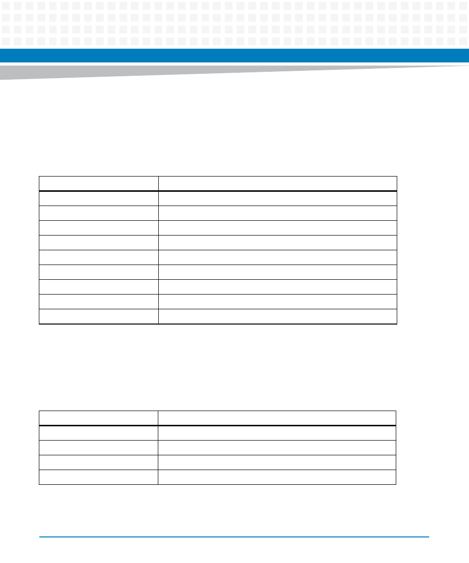
Serial Port Connector (COM1/J1)
There is one front access asynchronous serial port interface (SP0) that is routed to the
mini DB-9 front-panel connector. You can use the Artesyn part SERIAL-MINI-D2 to convert to a
DB9 male connector. The pin assignments for these connectors are as follows:
3.3.3.5
USB Connector (J2)
There is one USB Type A connector located on the MVME7100 front panel. The pin assignments
are as follows:
Table 3-12 COM1 Port Connector Pin Assignments
Pin
Signal
1
No connect
2
RX
3
TX
4
No Connect
5
GND
6
No Connect
7
RTS
8
CTS
9
No Connect
Table 3-13 USB Connector (J2) Pin Assignments
Pin
Signal
1
USB_VBUS (+5.0V)
2
USB_DATA-
3
USB_DATA+
4
GND
Advertising