3 serial port connectors (com2–com5/j1a-d), 6 pmc input/output module, Table 5-8 – Artesyn MVME7100 Single Board Computer Installation and Use (June 2014) User Manual
Page 91: Com port connector pin assignments, Pmc input/output module, Transition module
Transition Module
MVME7100 Single Board Computer Installation and Use (6806800E08D)
91
5.5.3
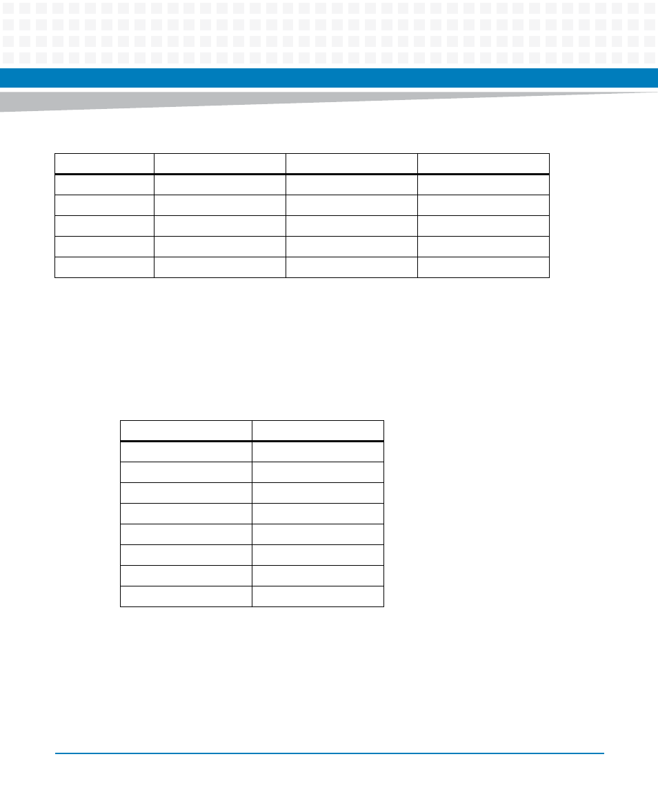
Serial Port Connectors (COM2–COM5/J1A-D)
The MVME7100 routes four asynchronous serial port interfaces, SP1 – SP4, to the VMEbus P2
connector. The MVME7216E routes these from the P2 connector to the RJ-45 connectors on
RTM panel. The pin assignments for these connectors are as follows:
5.6
PMC Input/Output Module
If a PMC Input/output Module (PIM) has already been installed on the MVME7216E, or you are
installing a transition module as it has been shipped from the factory, disregard this procedure
and refer to
4
MDIO1-
_DC+
Not Used
5
MDIO2+
_DC-
Not Used
6
MDIO2-
_DB-
RD-
7
MDIO3+
_DD+
Not Used
8
MDIO3-
_DD-
Not Used
Table 5-7 Ethernet Connectors Pin Assignment
Pin #
Signal
1000 Mb/s
10/100 Mb/s
Table 5-8 COM Port Connector Pin Assignments
Pin
Signal
1
No connect
2
RTS
3
GND
4
TX
5
RX
6
GND
7
CTS
8
No connect