2 transition module layout, Figure 5-1, Component layout – Artesyn MVME7100 Single Board Computer Installation and Use (June 2014) User Manual
Page 84: Transition module
Advertising
Transition Module
MVME7100 Single Board Computer Installation and Use (6806800E08D)
84
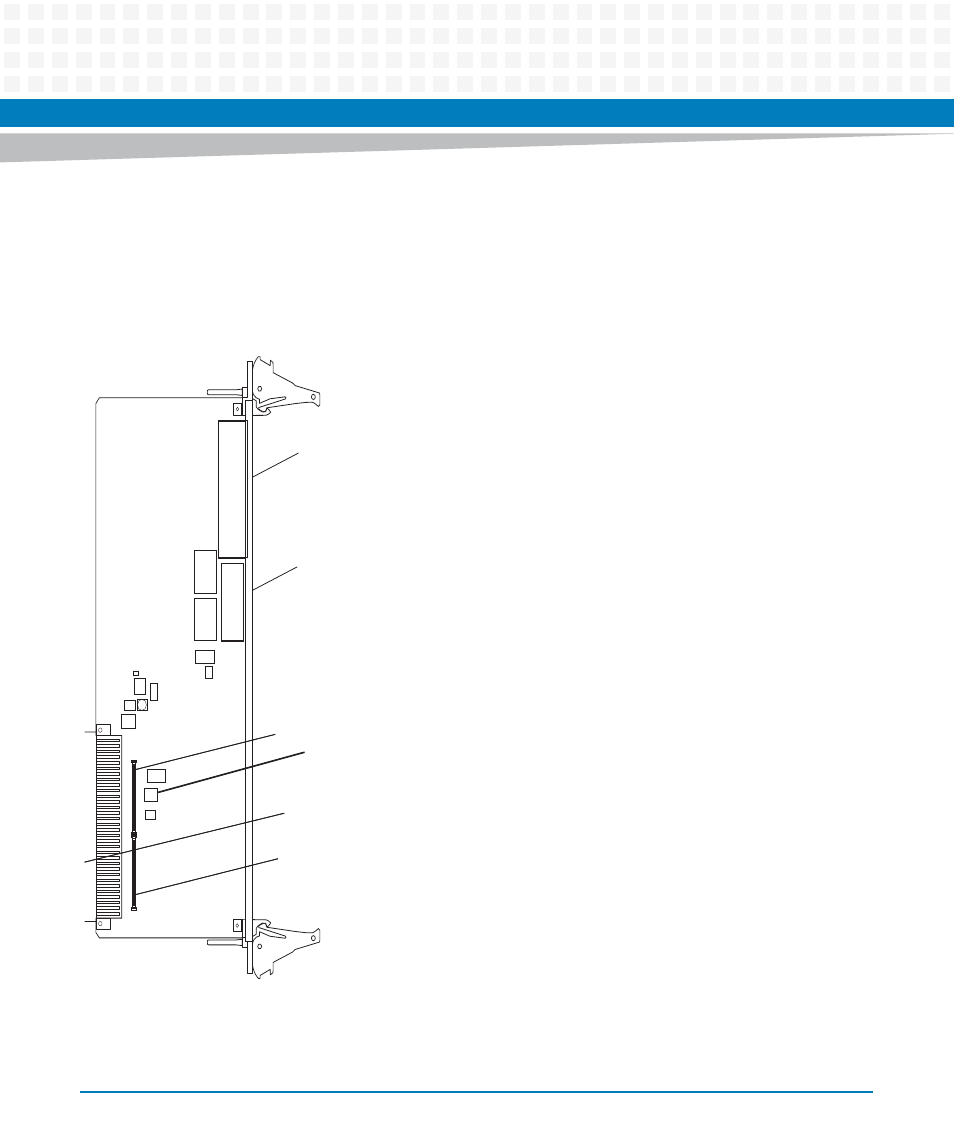
5.2
Transition Module Layout
The following illustration shows the component layout and connectors on the MVME7216E
transition module.
Figure 5-1
Component Layout
J14
J10
P2
U2
S1
U4
T1
J1
J2
C38
C25
T2
C38
U1
C39
L1
L2
C1
S1 SMT Switch
Advertising