14 stove installation, Mobile home requirements – Avalon Firestyles 1250 Wood Stove User Manual
Page 14
14 Stove
Installation
(for qualified installers only)
© Travis Industries
100-01178
4081029
Mobile Home Requirements
Outside air must be installed - see "Outside Air Requirements" on page 12.
Chimney connector and chimney must be one of the following types:
AMERI-TEC model DCC with model HS chimney
DURAVENT model DVL with DURATEC or DURA-PLUS chimney
GSW Super Chimney Twenty-One connected directly to appliance
I.C.C. Excel (2100-2 Can.) (103-HT USA) chimney with HP connector
METALFAB model DW connector with TG chimney
OLIVER MACLEOD PROVENT model PV connector with model 3103 chimney
SECURITY model DP connector with SECURITY model ASHT or S2100 chimney
SELKIRK METALBESTOS model DS connector with model SSII chimney
Standard Masonry Chimney with any one of the above listed connectors
NOTE: Reduced clearance connectors may not connect to the flue collar – an appliance adapter may be required.
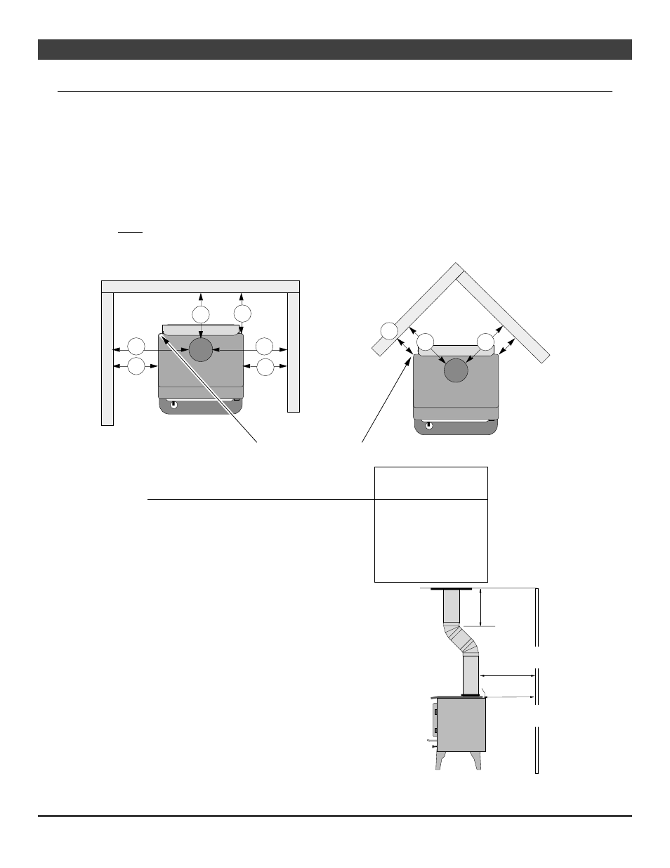
Stove placement must maintain the following clearances to combustibles (drywall, furniture, etc.):
Figure 10
Minimum Clearance
(See the illustration above)
Reduced Clearance
Connector
A
Sidewall to stove
18"
457mm
B
Backwall to stove
10-1/2" 267mm
C
Cornerwall to stove
10"
254mm
D
Connector to sidewall
26-1/2" 673mm
E
Connector to backwall
11-1/4" 286mm
F
Connector to cornerwall
17-1/4” 438mm
If using offsets, use the connector clearance listed in Figure 11,
not the connector manufacturer's clearance.
The appliance must be secured to the floor (consult your
building official). Secure the outside air boot to the floor and
stove to insure the stove does not dislocate.
Mobile home installations require a spark arrester at the
chimney termination.
The appliance must be grounded to the chassis of the mobile
home (consult your building official).
WARNING: DO NOT INSTALL IN SLEEPING ROOM.
CAUTION: THE STRUCTURAL INTEGRITY OF THE
MOBILE HOME FLOOR, WALL, AND CEILING/ROOF MUST
BE MAINTAINED.
Figure 11
STRAIGHT INSTALLATION
CORNER
INSTALLATION
A
B
D
E
A
D
F
F
NOTE: Measure rear clearances from the edge of the stove top, not the rear heat shield.
C
12” Min.
(305mm)
Connector Clearance
(as outlined above)
Stove Clearance
(as outlined above)