Human-machine interface, Controls and indicators, Section 2 – Basler Electric BE1-64F User Manual
Page 13: Human-machine interface -1, Controls and indicators -1
SECTION 2
• HUMAN-MACHINE INTERFACE
CONTROLS AND INDICATORS
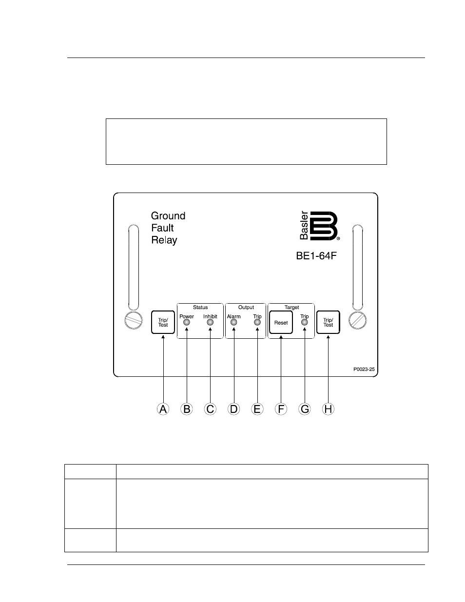
The BE1-64F human-machine interface (HMI) consists of pushbuttons and light-emitting diode (LED)
indicators located on the relay front panel. Figure 2-1 illustrates the BE1-64F HMI. Table 2-1 references
the locators in Figure 2-1 and provides a description of each BE1-64F control and indicator.
Figure 2-1. BE1-64F Controls and Indicators
Table 2-1. BE1-64F Control and Indicator Descriptions
Locator
Description
A
Trip/Test Pushbutton. Simultaneously pushing the two Trip/Test pushbuttons (locators A
and H) causes the Ground Trip output contacts to close, the Pre-Alarm output contacts to
close, the Trip Output indicator (locator E) to light, the Alarm output indicator (locator D) to
light, and the Trip Target indicator (locator G) to latch on. This control is not provided on
BE1-64F relays with part number 9367200104.
B
Power Status Indicator. This green LED lights when operating power is applied to the
relay.
NOTE
Because BE1-64F relays with part number 9367200104 are not equipped with
Trip/Test pushbuttons, locators A and H in Figure 2-1 and Table 2-1 do not apply
to these relays.
9367200990 Rev B
BE1-64F Human-Machine Interface
2-1