Installation, Mounting, Section 4 – Basler Electric BE1-64F User Manual
Page 19: Installation -1, Mounting -1, Storage -4, Pre-alarm jumper -4, Connections -5
Advertising
9367200990 Rev B
BE1-64F Installation
4-1
SECTION 4
INSTALLATION
MOUNTING
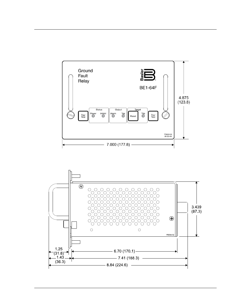
Figures 4-1 through 4-3 show the overall dimensions of the BE1-64F. Figure 4-1 shows the front view,
Figure 4-2 shows the side view, and Figure 4-3 shows the top view. A panel cutting and drilling diagram is
provided in Figure 4-4. All dimensions are shown in inches with millimeters in parenthesis.
Figure 4-1. BE1-64F Dimensions, Front View
Figure 4-2. BE1-64F Dimensions, Side View
Advertising