2 - controls and indicators, Introduction, Section 2 – Basler Electric BE1-40Q User Manual
Page 15: Controls and indicators -1
SECTION 2
• CONTROLS AND INDICATORS
INTRODUCTION
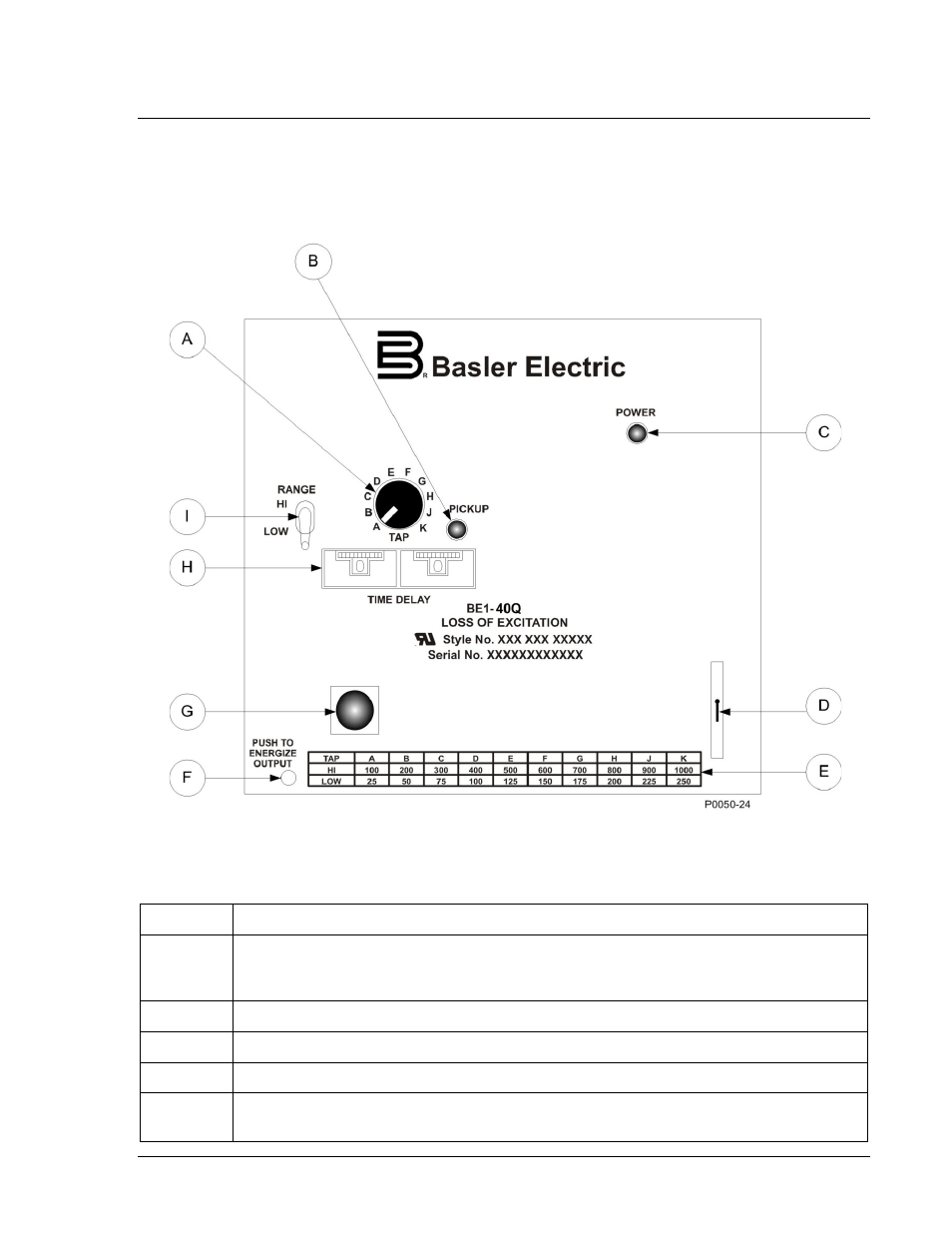
All BE1-40Q controls and indicators are located on the front panel. The controls and indicators are shown
in Figure 2-1 and described in Table 2-1. Figure 2-1 illustrates a relay with the maximum number of
controls and indicators. Your relay may not have all of the controls and indicators shown and described
here.
Figure 2-1. BE1-40Q Controls and Indicators
Table 2-1. Control and Indicator Descriptions
Locator
Description
A
Tap Switch. A ten-position rotary switch sets the pickup point when used in conjunction
with the Range switch (see Locator I). Pickup levels (in vars) are labeled on the Tap
Range Chart (see Locator E).
B
Pickup Indicator. LED illuminates to indicate that the pickup level has been exceeded.
C
Power Indicator. This red LED lights when operating power is applied to the relay.
D
Target Reset Switch. This switch is operated to reset the target indicator.
E
Tap Range Chart. Provides an index of reactive power levels (in vars) that correspond to
the Tap switch positions.
9171500990 Rev N
BE1-40Q Controls and Indicators
2-1