Timing verification, Relay characteristics verification, Preliminary – Basler Electric BE1-40Q User Manual
Page 42: Timing, Verification, Relay, Characteristics
Step 9. Repeat Steps 7 and 8 for each TAP setting, verifying both the HI and LOW range setpoints. The
pickup tolerance should be
±2% of the front panel setting or 0.1 var, whichever is greater.
Timing Verification
Step 1. Connect the test circuit as shown in Figure 5-2.
Step 2. Connect a timer to record the time interval from application of the test current that will be
applied in Step 6, to the change of state of the output relay. If a normally open contact has been
selected, a trip will occur when the contact closes; normally closed contacts will open to trip.
Step 3. Make the following front panel adjustments on the BE1-40Q relay:
RANGE switch - LOW position
TAP switch - Position A (minimum)
TIME DELAY switches - 11 (1.1 second)
Step 4. Apply appropriate operating power, depending on the power supply option, to terminals 3 and 4.
The POWER LED should illuminate.
Step 5. Adjust the voltage source to the nominal value of the sensing input as designated by the second
digit of the style number.
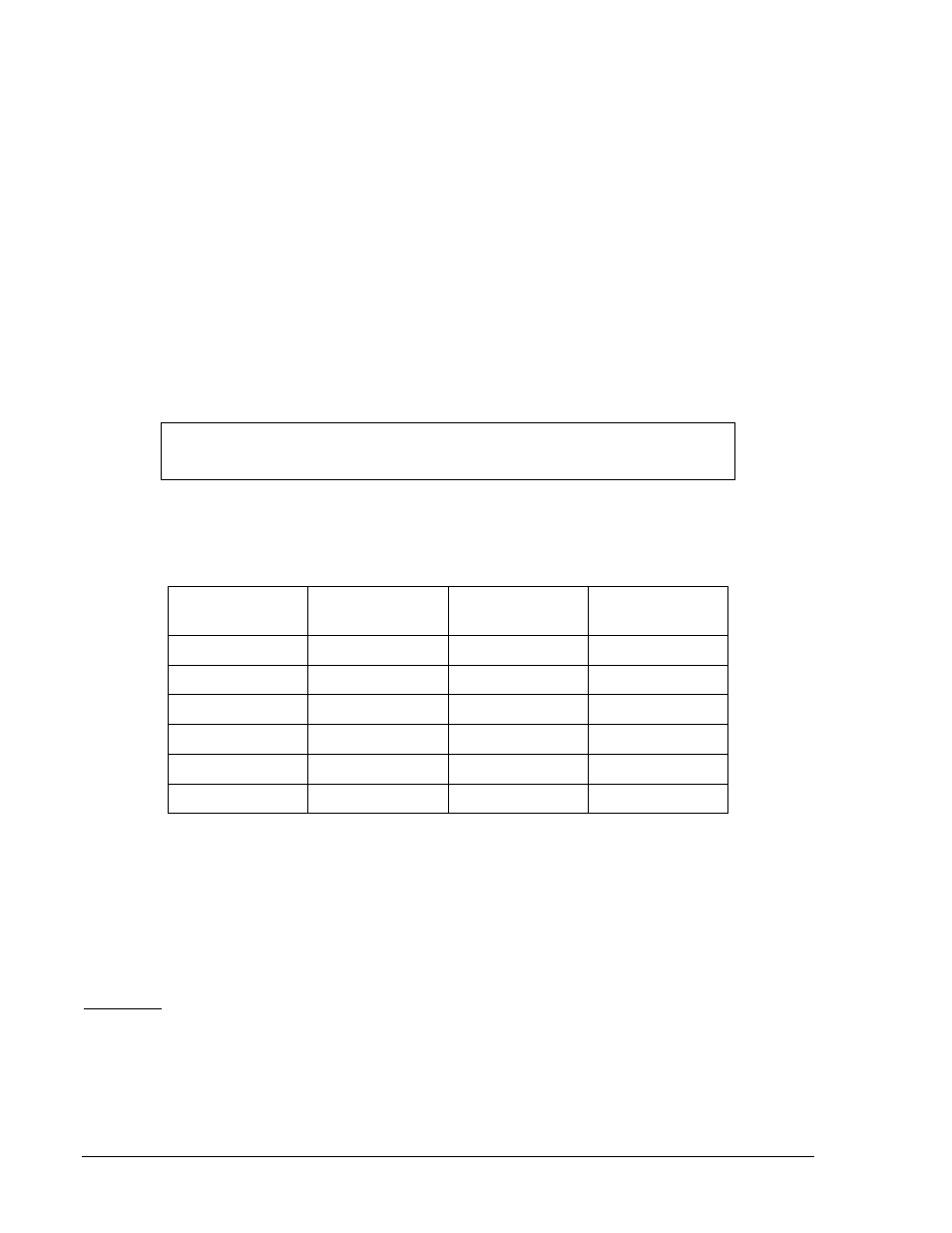
Step 6. Adjust the current source to produce a 60
° lagging current that steps from zero magnitude to the
test current value shown in Table 5-2.
Table 5-2. Test Current
Second Digit of
Style Number
Nominal Ac
Voltage
Pickup Current
Test Current
2
120
0.072 A
0.144 A
3
120
0.361 A
0.722 A
5
208
0.083 A
0.166 A
6
208
0.416 A
0.832 A
8
240
0.072 A
0.144 A
9
240
0.361 A
0.722 A
Step 7. The actual time delay should be 1.05 to 1.15 seconds.
Step 8. Adjust the TIME DELAY switches to a setting of 55 (5.5 seconds), and repeat Step 6. The time
delay should be 5.22 to 5.77 seconds.
Step 9. Adjust the TIME DELAY switches to a setting of 99 (9.9 seconds), and repeat Step 6. The time
delay should be 9.40 to 10.39 seconds.
Relay Characteristics Verification
Preliminary
Step 1. Connect the test circuit shown in Figure 5-2.
Step 2. Adjust the BE1-40Q relay for the desired pickup value as specified by the generator application
or the test setup capabilities.
Step 3. Adjust the TIME DELAY switches to a minimum value (e.g., 0.1, 0.2, or 0.3 seconds).
Step 4. Adjust the voltage source to the nominal value of the sensing input as designated by the second
digit of the style number, at a leading phase angle of 150
°.
NOTE
The test current given in Table 5-2 is twice the pickup current.
5-4
BE1-40Q Setting and Testing
9171500990 Rev N