Revision history – Basler Electric BE1-40Q User Manual
Page 5
9171500990 Rev N
BE1-40Q Introduction
iii
REVISION HISTORY
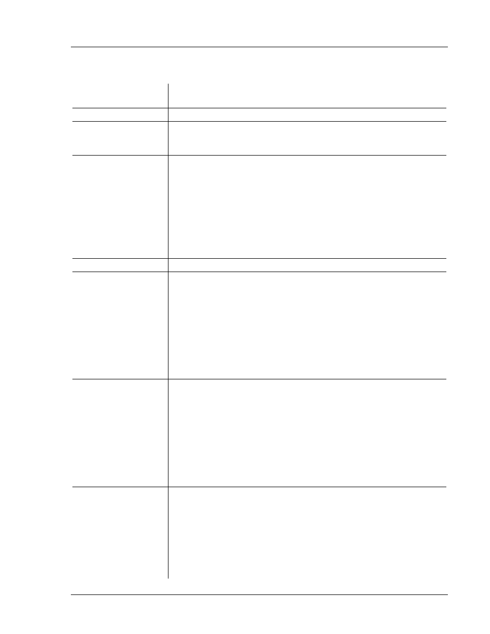
The following information provides a historical summary of the changes made to the BE1-40Q instruction
manual (9171500990). Revisions are listed in reverse chronological order.
Manual
Revision and Date
Change
N, 12/12
Standardized case and cover drawings in Section 4.
M, 01/11
Updated equations in Note 1 under Figure 5-2.
Improved timing specs under Operational Test, Timing Verification in
Section 5.
L, 09/07
Added manual part number and revision to footers.
Updated Output Contact ratings in Section 1.
Updated Power Supply Burden data in Section 1.
Updated front panel illustrations to show laser graphics.
Updated Target Indicator description in Section 3.
Added GOST-R to Section 1, General Information.
Moved content of Section 7, Manual Change Information to Manual
Introduction.
Moved content of Section 6, Maintenance to Section 4, Installation.
K, 02/01
Updated S1 case drawings in Section 4 to the most recent drawings.
J, 10/98
Corrected Voltage Sensing in Specifications from “Each have a
burden that is less than 0.1 ohm over the” to “Each have a burden
that is less than 1 VA over the”.
Deleted 500 Vdc from Resistive Output Circuits.
Deleted all references to Service Manual.
Updated Style Number Identification Chart by changing Power Supply
Type T from “230 Vac” to “240 Vac”.
Added new power supply information to Specifications and Section 3
starting with “Basler Electric enhanced the power supply design…”
Changed the format of the manual.
H, 03/95
Changed Section 1, General Information, Specifications, Output
Circuits and Isolation.
Added phase rotation sensitivity information to Section 3, Functional
Description.
Changed Section 4, Installation, Dielectric Test, to reflect specification
changes.
Corrected Figure 4-1 and changed Figure 5-2, note 2.
Corrected typographical error in Table 5-4, Reactive Power (Vars),
+120.
Corrected typographical error in Section 6, Maintenance, General.
G, 01/94
Deleted references to mho characteristic.
Corrected Figure 4-3 (Sensing Input Test Setup), current sensing
input terminals 8 and 9 were reversed on earlier versions;
renumbered equations; updated format; and added new internal
connection diagrams Figures 4-3 through 4-5, added new mounting
diagrams Figures 4-6 through 4-14.
Added new Section 5, Setting and Testing, moved appropriate data
from Section 4 into Section 5, and changed Section 5 and 6 to
Section 6 and 7.