Setting the relay, Setting example for sensing input types e and f – Basler Electric BE1-60 User Manual
Page 10
1-2
BE1-60 General Information
9170700990 Rev D
If a power potential transformer fuse opens, the resulting unbalanced condition may cause excessive
heating in the power stage of the static exciter. This condition would warrant an alarm indication and an
orderly shutdown of the unit. The BE1-60 Circuit 1 output would accomplish this task and the Circuit 1
target would indicate that an open power potential transformer fuse had initiated the correct shutdown
sequence.
If a sensing potential transformer fuse opens, the static exciter (with three-phase sensing) output would
increase to maximum in an attempt to restore the sensed voltage to the proper level. For this condition,
the BE1-60 would initiate an emergency shutdown of the unit and issue an alarm. The BE1-60 Circuit 2
output would accomplish this task and the Circuit 2 target would indicate that an open sensing potential
transformer fuse had initiated the correct shutdown sequence.
Also, since the same potential source provides the control
1
or restraint
2
input to the time-overcurrent
relays, false tripping of the unit may result due to operation of the overcurrent relays. This is undesirable
because the overcurrent relay target would give a false indication of the reason for tripping. To prevent
this, the BE1-60 Circuit 2 output would be required to block operation of the overcurrent relays. This
would be accomplished by opening a normally-closed contact from the BE1-60, which is in series with the
tripping outputs of the overcurrent relays.
1
If the overcurrent functions were voltage controlled and the output current exceeded the relay
pickup setting, a loss of power potential would allow this overcurrent function to pick up and
start timing. Without the inhibit from the BE1-60, tripping would result.
2
If the overcurrent functions were voltage restrained, the loss of restraint potential would
increase the sensitivity of the relay (2½ times setting) and the relay would pick up and start
timing. Without the inhibit from the BE1-60, tripping would result.
SETTING THE RELAY
When setting the relay, consideration should be given to the maximum voltage excursions permitted for
normal operating conditions. For example, if the power potential transformer output varies 5% from
machine no-load to machine full-load, the setting must accommodate this fluctuation.
Also note that since both BE1-60 inputs (Circuit 1 and Circuit 2) are monitoring essentially the same
voltage, BE1-60 tripping will not occur for system faults.
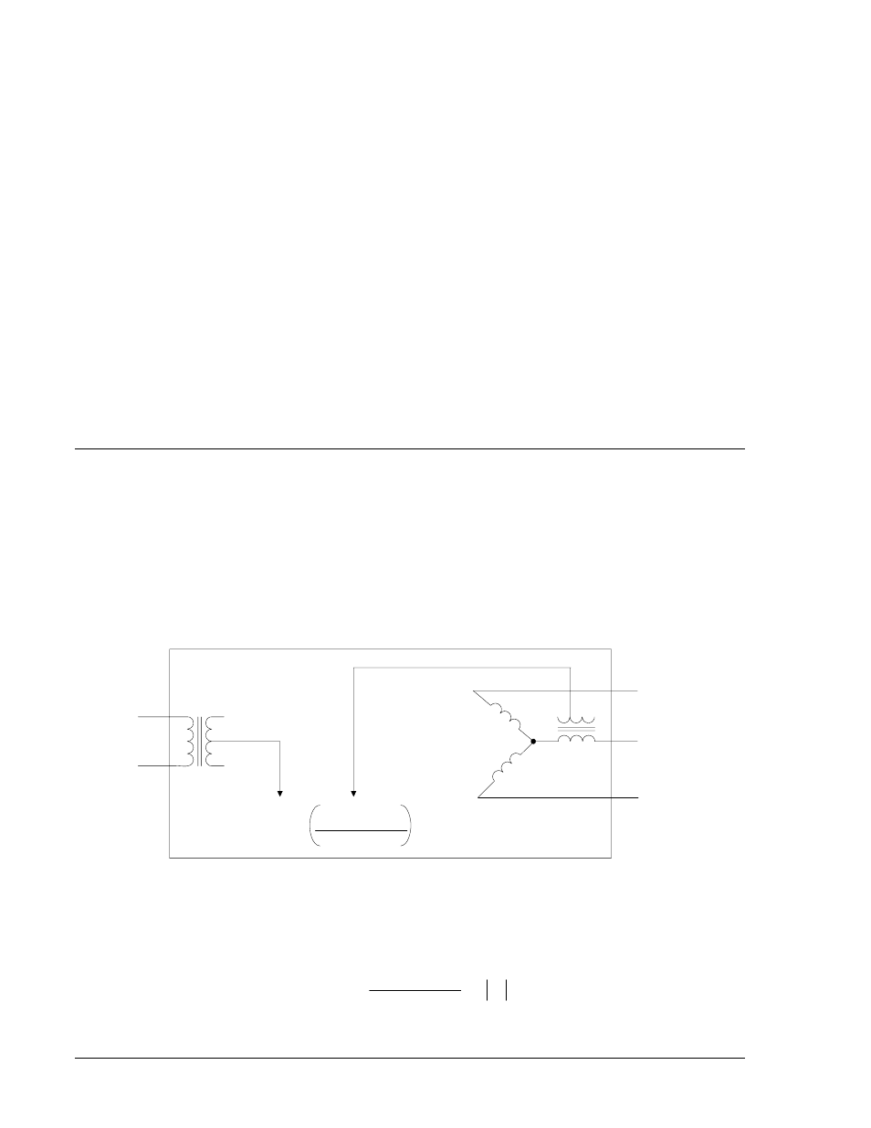
BE1-60 relays with sensing input type E (single-phase to three-phase wye) or F (single-phase to three-
phase delta) apply the three-phase input to an internal, Scott (T-connected) transformer. This transformer
produces a single-phase voltage that is proportional to the average of the three-phase voltages shown in
Figure 1-2. This decreases the relay’s sensitivity as illustrated by the following example.
CIRCUIT 1
INPUT
CIRCUIT 2
INPUT
A
B
C
D2817-19
07-17-98
(V
1
) - V
2A
+V
2B
+V
2C
=
ΔV
3
Figure 1-2. Internal Voltage Sensing and Measurement for Sensing Types E and F
Setting Example for Sensing Input Types E and F
If a fuse blows in phase C of Circuit 2, an apparent difference of 40 volts is produced within the relay.
( )
40
3
0
120
120
120
=
⎟
⎠
⎞
⎜
⎝
⎛
+
+
−