Functional description, Introduction, Step-down transformers – Basler Electric BE1-60 User Manual
Page 17: Full-wave rectifiers and integrators, Differential amplifiers, Section 3, Functional description -1
9170700990 Rev D
BE1-60 Functional Description
3-1
SECTION 3
• FUNCTIONAL DESCRIPTION
INTRODUCTION
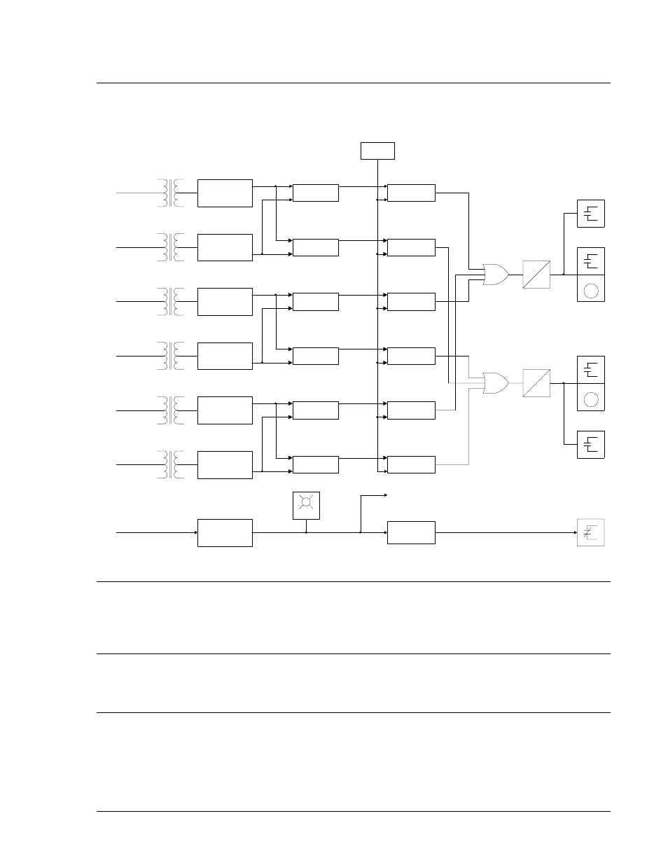
BE1-60 Voltage Balance Relay functions and operating features are illustrated in Figure 3-1 and
described in the following paragraphs.
1A
2A
1B
2B
1C
2C
FULL-WAVE
RECTIFIER AND
INTEGRATOR
DIFFERENTIAL
AMPLIFIER
LIMIT
COMPARATOR
LIMIT
SETTING
FULL-WAVE
RECTIFIER AND
INTEGRATOR
DIFFERENTIAL
AMPLIFIER
LIMIT
COMPARATOR
FULL-WAVE
RECTIFIER AND
INTEGRATOR
DIFFERENTIAL
AMPLIFIER
LIMIT
COMPARATOR
FULL-WAVE
RECTIFIER AND
INTEGRATOR
DIFFERENTIAL
AMPLIFIER
LIMIT
COMPARATOR
FULL-WAVE
RECTIFIER AND
INTEGRATOR
DIFFERENTIAL
AMPLIFIER
LIMIT
COMPARATOR
FULL-WAVE
RECTIFIER AND
INTEGRATOR
DIFFERENTIAL
AMPLIFIER
LIMIT
COMPARATOR
V
2A
-V
1A
>0
ΔV
V
1A
-V
2A
>0
V
2B
-V
1B
>0
V
1B
-V
2B
>0
V
2C
-V
1C
>0
V
1c
-V
2C
>0
0
0.75
0
0.75
TARGET
TARGET
AUX.
CIRCUIT 1
AUX.
CIRCUIT 2
POWER
SUPPLY
POWER
SUPPLY
SENSOR
POWER
SUPPLY
STATUS
TO INTERNAL CIRCUITRY
POWER
ΔV > LIMIT SETTING
D2817-17
07-14-98
Figure 3-1. BE1-60 Function Block Diagram
STEP-DOWN TRANSFORMERS
Voltage received from the power system potential transformers is applied to sensing transformers within
the BE1-60 relay. The voltage is stepped down to appropriate levels and supplied to full-wave rectifier
circuits within the relay.
FULL-WAVE RECTIFIERS AND INTEGRATORS
Outputs from the step-down transformers are full-wave rectified and then integrated. The integrator
circuits establish a dc voltage that represents the magnitude of the associated sensing input.
DIFFERENTIAL AMPLIFIERS
The representative dc voltage from each integrator is applied to a pair of differential amplifiers. Each
differential amplifier pair is dedicated to a particular phase of the monitored system. The pair determines
which monitored circuit has the lower voltage (for that phase) and the difference in magnitude. For
example, if phase A of Circuit 1 is lower than phase A of Circuit 2, then V
2A
– V
1A
= V.